This special page shows all uploaded files.
| Date | Name | Thumbnail | Size | Description | Versions |
|---|---|---|---|---|---|
| 01:06, 26 November 2011 | H-BridgeLeftRight.svg (file) |  |
44 KB | Simple H-Bridge of four switches. | 1 |
| 01:15, 26 November 2011 | H-BridgeLeftRight.png (file) |  |
25 KB | 1 | |
| 01:20, 26 November 2011 | Series-Circuit 01 Lamps.png (file) | 21 KB | Series circuit of equal lamps sharing voltage. | 1 | |
| 01:23, 26 November 2011 | Series-Circuit 02 Lamps Voltages add.png (file) |  |
26 KB | Series circuit of 8 Lamps on a 12V voltage source + voltage Meters | 1 |
| 12:46, 15 December 2011 | Darlington Array ULN2003 and 6-Wire-Stepper.png (file) |  |
56 KB | 2 | |
| 13:41, 15 December 2011 | Poti Transistor Motor 5V.png (file) |  |
70 KB | 1 | |
| 13:50, 15 December 2011 | Motor Transistor PWM.png (file) |  |
67 KB | 1 | |
| 13:57, 5 January 2012 | Darlington LED touch Schaltplan.png (file) |  |
73 KB | 1 | |
| 13:58, 5 January 2012 | Smooth PWM Capacitor Schaltplan.png (file) |  |
80 KB | 1 | |
| 13:59, 5 January 2012 | Button pullUp Schaltplan.png (file) |  |
61 KB | 1 | |
| 14:00, 5 January 2012 | Button pullDown Schaltplan.png (file) |  |
59 KB | 1 | |
| 14:01, 5 January 2012 | Touch Button Input Darlington Schaltplan.png (file) |  |
72 KB | 1 | |
| 12:04, 12 January 2012 | Pd-arduinoOscilloscope.zip (file) | 2 KB | 1 | ||
| 13:59, 26 January 2012 | Compare AnalogValue Digital Input Schaltplan.png (file) |  |
74 KB | 1 | |
| 14:00, 26 January 2012 | Measure Capacity Arduino Resistor Capacitor Schaltplan.png (file) |  |
69 KB | 1 | |
| 14:00, 26 January 2012 | Debounce Button Capacitor Resistors Schaltplan.png (file) |  |
72 KB | 1 | |
| 12:33, 28 January 2012 | 2012 01 26 Tafel LED Vorwiderstand.svg (file) |  |
510 KB | Mitschrieb des Tafelbilds - experimentell. | 1 |
| 19:36, 7 February 2012 | Wago-Klemme-3pol.JPG (file) |  |
58 KB | 1 | |
| 19:37, 7 February 2012 | Subd-9pol-mf.JPG (file) |  |
89 KB | 1 | |
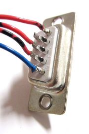
| 19:37, 7 February 2012 | Subd-9pol.JPG (file) |  |
166 KB | 1 | |
| 19:37, 7 February 2012 | Stiftleiste-Gewinkelt.JPG (file) |  |
58 KB | 1 | |
| 19:37, 7 February 2012 | Schraubklemmleiste.JPG (file) |  |
166 KB | 1 | |
| 19:37, 7 February 2012 | Schraubklemmleiste-auf-Platine.JPG (file) |  |
68 KB | 1 | |
| 19:37, 7 February 2012 | Sandwichleiste-Zweireihig.JPG (file) |  |
132 KB | 1 | |
| 19:37, 7 February 2012 | Ringkabelschuh.JPG (file) |  |
42 KB | 1 | |
| 19:37, 7 February 2012 | PSK-Set-Zusammenbau.JPG (file) |  |
88 KB | 1 | |
| 19:37, 7 February 2012 | Gabelkabelschuh.JPG (file) |  |
80 KB | 1 | |
| 19:37, 7 February 2012 | Flachsteckhülse.JPG (file) |  |
64 KB | 1 | |
| 19:37, 7 February 2012 | Experimentierplatinen-Lochraster-Streifenraster.JPG (file) |  |
517 KB | 1 | |
| 19:38, 7 February 2012 | Buchsenleisten Einreihig.JPG (file) |  |
172 KB | 1 | |
| 19:38, 7 February 2012 | Aderendhülse-unpassend.JPG (file) |  |
42 KB | 1 | |
| 19:38, 7 February 2012 | Aderendhülse-Lüsterklemme-2.JPG (file) |  |
94 KB | 1 | |
| 19:38, 7 February 2012 | Aderendhülse-Lüsterklemme-1.JPG (file) |  |
95 KB | 1 | |
| 19:38, 7 February 2012 | Aderendhuelse-passend.JPG (file) |  |
52 KB | 1 | |
| 10:50, 3 May 2012 | LED Pin 3 Potentiometer A0 Steckplatine.png (file) |  |
88 KB | 1 | |
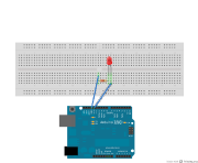
| 10:54, 3 May 2012 | LED Pin 13 Steckplatine.png (file) |  |
68 KB | 2 | |
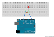
| 10:55, 3 May 2012 | LED Pin 3 Steckplatine.png (file) |  |
82 KB | 2 | |
| 13:05, 9 May 2012 | Resistive Sensor Steckplatine.png (file) |  |
60 KB | How to wire a resistive sensor | 1 |
| 14:05, 9 May 2012 | Button 1k Pullup Steckplatine.png (file) |  |
67 KB | How to wire a button or switch to Arduino. | 1 |
| 14:19, 9 May 2012 | Potentiometer A0 Serial Steckplatine.png (file) |  |
51 KB | 1 | |
| 00:32, 17 May 2012 | Opencollector Schaltplan.png (file) |  |
32 KB | wiring an open collector output to a microcontroller input - using an external pull up resistor. | 1 |
| 23:32, 21 May 2012 | Emitter Follower 3V 9V Poti Motor Schaltplan-modified.png (file) |  |
18 KB | Example circuit of an emitter follower using a potentiometer as voltage divider and 2 different batteries. | 1 |
| 23:34, 21 May 2012 | Emitter Circuit Arduino Motor Schaltplan-modified.png (file) |  |
33 KB | Example showing the usage of a transistor to switch a load (a motor) from a low control voltage and a higher supply voltage for the motor. | 1 |
| 23:36, 21 May 2012 | Emitter Circuit Simple Schaltplan-modified.png (file) |  |
18 KB | Simplest possible NPN emitter circuit. | 1 |
| 23:37, 21 May 2012 | Emitter Follower Simple Schaltplan-modified.png (file) |  |
9 KB | Simplest possible NPN transistor emitter follower circuit | 1 |
| 11:20, 21 June 2012 | 4 Buttons Internal Pullup schem.png (file) |  |
34 KB | 4 Buttons on an Arduino - using the internal pull up resistors. | 1 |
| 15:46, 12 July 2012 | InteraktiveEletronik2012Showreel.png (file) |  |
2.78 MB | 1 | |
| 08:19, 13 July 2012 | InteraktiveEletronik2012Showreel0.png (file) |  |
78 KB | 2 | |
| 08:19, 13 July 2012 | InteraktiveEletronik2012Showreel1.png (file) |  |
112 KB | 2 | |
| 08:19, 13 July 2012 | InteraktiveEletronik2012Showreel2.png (file) |  |
948 KB | 2 |