m (→Build) |
|||
| (15 intermediate revisions by the same user not shown) | |||
| Line 4: | Line 4: | ||
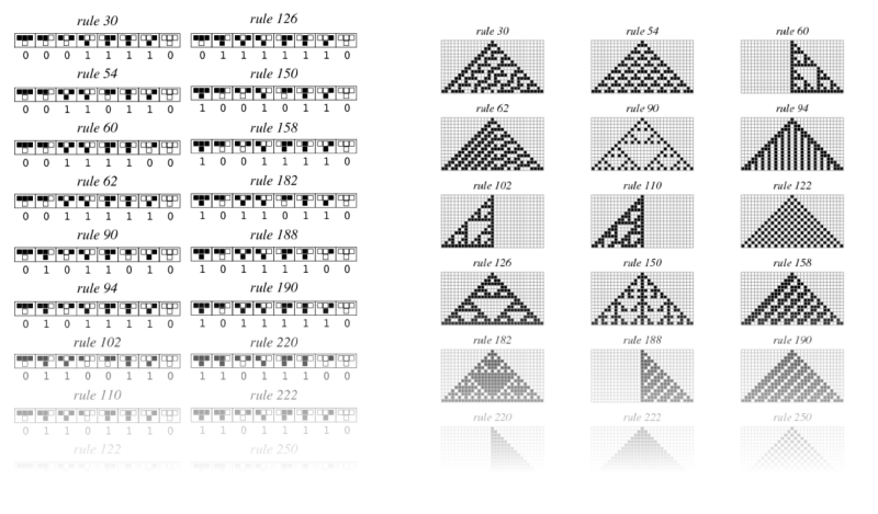
[[File:all_rules.png|800px]] | [[File:all_rules.png|800px]] | ||
----- | |||
==Schematic== | ==Schematic== | ||
To keep the controls simple, the only inputs used are two potentiometers and a button. for the LED matrix a preassebled 8x8 matrix with a MAX7219 controller are mounted through the back to make it shine through the PCB. Thus five holes have to be added for the five pins of the MAX7219 have to be added. | To keep the controls simple, the only inputs used are two potentiometers and a button. for the LED matrix a preassebled 8x8 matrix with a MAX7219 controller are mounted through the back to make it shine through the PCB. Thus five holes have to be added for the five pins of the MAX7219 have to be added. | ||
[[File:Schematic.PNG|800px]] | [[File:Schematic.PNG|800px]] | ||
----- | |||
==PCB== | ==PCB== | ||
| Line 13: | Line 17: | ||
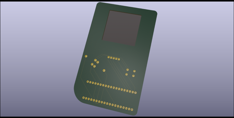
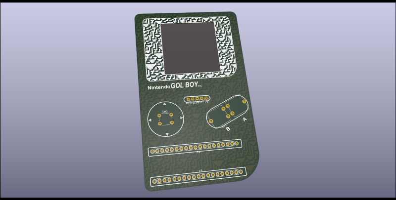
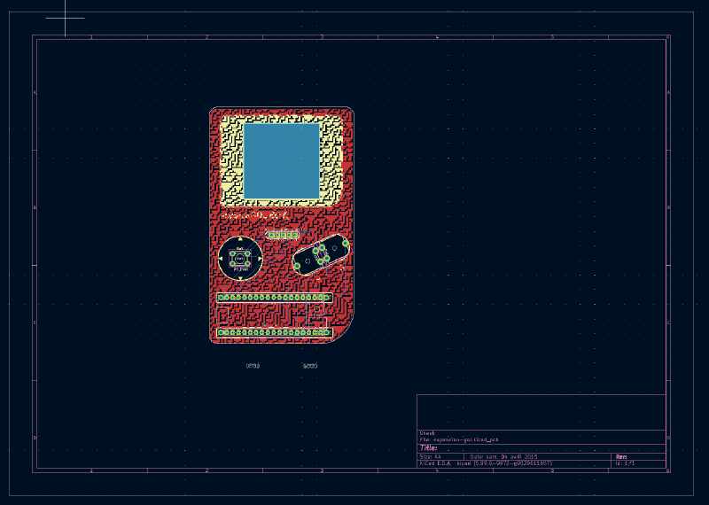
After a rough layout in PCBnew, I went to Inkscape, traced an old GameBoy and began to make outlines for the edge-cuts and silkscreen layer. After importing the general shape, I layouted all the mounting holes and pins and began to wire everything on the backside of the PCB. I left a window in the mask-layer, where the LED matrix is going to be mounted to and surrounded every component with a symbolic outline in the silkscreen-layer. | After a rough layout in PCBnew, I went to Inkscape, traced an old GameBoy and began to make outlines for the edge-cuts and silkscreen layer. After importing the general shape, I layouted all the mounting holes and pins and began to wire everything on the backside of the PCB. I left a window in the mask-layer, where the LED matrix is going to be mounted to and surrounded every component with a symbolic outline in the silkscreen-layer. | ||
[[File:pcb_new.PNG|800px]] | [[File:pcb_new.PNG|800px]] | ||
----- | |||
===Generation=== | ===Generation=== | ||
To fill the general outline with texture, a 1-dimensional cellular automata was used with random inputs and the infamous rule 30. I upscaled the resulting texture and imported it into Inkscape. The texture was then masked to exclude the immediate surroundings of the components. It was then once used for the silkscreen (just around the screen) and once for the front copper for the rest of the PCB. | To fill the general outline with texture, a 1-dimensional cellular automata was used with random inputs and the infamous rule 30. I upscaled the resulting texture and imported it into Inkscape. The texture was then masked to exclude the immediate surroundings of the components. It was then once used for the silkscreen (just around the screen) and once for the front copper for the rest of the PCB. | ||
[[File:rule30.png|600px]] | [[File:rule30.png|600px]] | ||
----- | |||
==Final Design== | ==Final Design== | ||
[[File:3d-back.png|800px]] | [[File:3d-back.png|800px]] | ||
[[File:3d-front.png|800px]] | [[File:3d-front.png|800px]] | ||
----- | |||
==Programming== | ==Programming== | ||
| Line 28: | Line 38: | ||
===MIDI=== | ===MIDI=== | ||
To send the state of the simulation using MIDI the library MIDIUSB (https://github.com/arduino-libraries/MIDIUSB) was used. The state of the simulation is mapped to chrods of a selected scale that are hardcoded in memory and can be send all at once or as an arpeggio. To map to the scales the state of the automata is interpreted as an 8-Bit number that is then mapped to the tone. The speed or time of the interval is controlled by the shield. | To send the state of the simulation using MIDI the library MIDIUSB (https://github.com/arduino-libraries/MIDIUSB) was used. The state of the simulation is mapped to chrods of a selected scale that are hardcoded in memory and can be send all at once or as an arpeggio. To map to the scales the state of the automata is interpreted as an 8-Bit number that is then mapped to the tone. The speed or time of the interval is controlled by the shield. | ||
----- | |||
==Parts== | ==Parts== | ||
| Line 35: | Line 47: | ||
* MAX7219 8x8 LED Matrix-Modul | * MAX7219 8x8 LED Matrix-Modul | ||
* Arduino Micro | * Arduino Micro | ||
----- | |||
==Build== | ==Build== | ||
[[File:PCB Arts -L.E.K Build.jpg| | [[File:PCB Arts -L.E.K Build.jpg|176px]][[File:PCB Arts -L.E.K Build 2.jpg|559px]] | ||
Due to an error I did on the left potentionmeter (missing connection). I was not able to follow my planned design and had to improvise. | Due to an error I did on the left potentionmeter (missing connection). I was not able to follow my planned design and had to improvise. | ||
To the same functionality as planned, I replaced the one potentiometer left with another button, giving me two buttons to work with. | To the same functionality as planned, I replaced the one potentiometer left with another button, giving me two buttons to work with. | ||
I sadly had to use cables for the LED Matrix and parts of the buttons, due to my GND and 5V+ beeing all connected to each other. | I sadly had to use cables for the LED Matrix and parts of the buttons, due to my GND and 5V+ beeing all connected to each other. | ||
The combination of lines and cables however works as intended. | The combination of lines and cables however works as intended. | ||
[[File:ezgif-6-ba2d047897d0.gif|360px]] | [[File:ezgif-6-ba2d047897d0.gif|360px]] | ||
[[File:ezgif-6-46dbab99ab2a.gif|360px]] | [[File:ezgif-6-46dbab99ab2a.gif|360px]] | ||
(GIFs, click to play) | (GIFs, click to play) | ||
----- | |||
==Usage== | |||
To use the build just plug it in using a micro-USB cable and enable it in the DAW as a Midi-Device (named Arduino Micro). | |||
Since the build only has two buttons (left and right) for many functionalities, alls buttons have multiple uses and combinations: | |||
* '''Click Left''' (Down, Up under 200ms): '''Next Chord''' | |||
* '''Hold Right & Click Left''' (Hold first): '''Previous Chord''' | |||
* '''Click Right''' (Down, Up under 200ms): '''Next Cellular Automata Rule''' (0-255 wraps around) | |||
* '''Hold Left & Click Right''' (Hold first): '''Previous Cellular Automata Rule''' (0-255 wraps around) | |||
* '''Hold Left''' (Longer than 500ms): '''Increase BPM''' | |||
* '''Hold Right''' (Longer than 500ms): '''Decrease BPM''' | |||
* '''Hold Left & Hold Right''' (Longer than 500ms): '''Start/Stop playing''' | |||
* '''Hold Left & Hold Right''' (Longer than 2000ms): Reset everything''' | |||
----- | |||
==Demonstration== | ==Demonstration== | ||
{{#ev:youtube|7doCJ39owTw|735}} | {{#ev:youtube|7doCJ39owTw|735}} | ||
----- | |||
==Further Reading:== | ==Further Reading:== | ||
Latest revision as of 17:44, 20 May 2021
GOL-Midi Semesterprojekt
Concept
In this project I wanted to revisit my first-semester project about generating sound using cellular automata. Instead of synthesizing the sound directly from the state of the cellular automata, I wanted to take advantage of using the MIDI-capabilities of the ATmega32U4 microcontroller and design a custom PCB for an Arduino Micro shield which controlls the simulation. The state of the simulation is then send as MIDI over the USB-C port of the Arduino, which can then be used as a MIDI-controller. For the design of the PCB I wanted to take a procedural approach aswell while keeping it simple but taking advantage of all the layers available. The custom PCB controlls the speed and rules used in the one-dimensional automata. To visualize the automate an 8x8 LED matrix is used.
Schematic
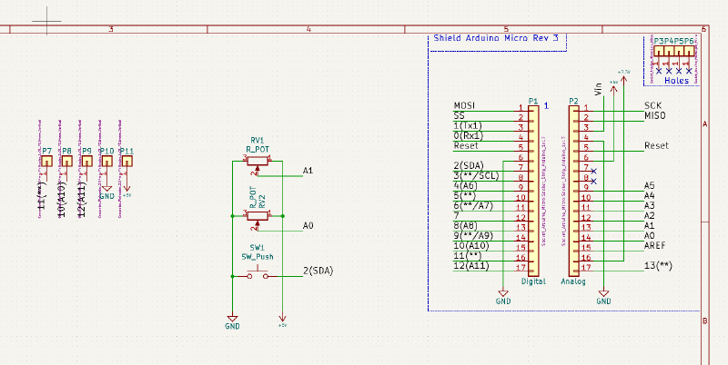
To keep the controls simple, the only inputs used are two potentiometers and a button. for the LED matrix a preassebled 8x8 matrix with a MAX7219 controller are mounted through the back to make it shine through the PCB. Thus five holes have to be added for the five pins of the MAX7219 have to be added.
PCB
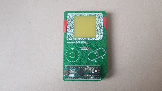
For the general PCB shape I wanted to use the retro-look of old hand-held game-consoles in combination with a texture that was generated by cellular automata.
After a rough layout in PCBnew, I went to Inkscape, traced an old GameBoy and began to make outlines for the edge-cuts and silkscreen layer. After importing the general shape, I layouted all the mounting holes and pins and began to wire everything on the backside of the PCB. I left a window in the mask-layer, where the LED matrix is going to be mounted to and surrounded every component with a symbolic outline in the silkscreen-layer.
Generation
To fill the general outline with texture, a 1-dimensional cellular automata was used with random inputs and the infamous rule 30. I upscaled the resulting texture and imported it into Inkscape. The texture was then masked to exclude the immediate surroundings of the components. It was then once used for the silkscreen (just around the screen) and once for the front copper for the rest of the PCB.

Final Design
Programming
Simulation
To efficiently simulate the 8-Bit automata the state of the cell and it's neighbours are interpreted as 3-Bit numbers that are then looked up in two arrays. One for the rules whether a cell is created and one for whether the cell should die. Rules for the automata can be changed using the shield.
MIDI
To send the state of the simulation using MIDI the library MIDIUSB (https://github.com/arduino-libraries/MIDIUSB) was used. The state of the simulation is mapped to chrods of a selected scale that are hardcoded in memory and can be send all at once or as an arpeggio. To map to the scales the state of the automata is interpreted as an 8-Bit number that is then mapped to the tone. The speed or time of the interval is controlled by the shield.
Parts
Besides the PCB the following parts are necessary:
- 2 Potentiometer
- Button 6mm
- MAX7219 8x8 LED Matrix-Modul
- Arduino Micro
Build
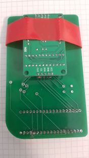
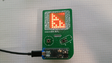
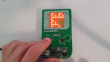
Due to an error I did on the left potentionmeter (missing connection). I was not able to follow my planned design and had to improvise. To the same functionality as planned, I replaced the one potentiometer left with another button, giving me two buttons to work with. I sadly had to use cables for the LED Matrix and parts of the buttons, due to my GND and 5V+ beeing all connected to each other. The combination of lines and cables however works as intended.
Usage
To use the build just plug it in using a micro-USB cable and enable it in the DAW as a Midi-Device (named Arduino Micro). Since the build only has two buttons (left and right) for many functionalities, alls buttons have multiple uses and combinations:
- Click Left (Down, Up under 200ms): Next Chord
- Hold Right & Click Left (Hold first): Previous Chord
- Click Right (Down, Up under 200ms): Next Cellular Automata Rule (0-255 wraps around)
- Hold Left & Click Right (Hold first): Previous Cellular Automata Rule (0-255 wraps around)
- Hold Left (Longer than 500ms): Increase BPM
- Hold Right (Longer than 500ms): Decrease BPM
- Hold Left & Hold Right (Longer than 500ms): Start/Stop playing
- Hold Left & Hold Right (Longer than 2000ms): Reset everything
