JinYunshui (talk | contribs) |
JinYunshui (talk | contribs) |
||
| (3 intermediate revisions by the same user not shown) | |||
| Line 1: | Line 1: | ||
==EHP - 3D Scaning Project== | ==EHP - 3D Scaning Project== | ||
[File:Laser_step0.png] | [[File:Laser_step0.png|700px]] | ||
<br> | <br> | ||
| Line 66: | Line 66: | ||
====Step 4 Building the Gears==== | ====Step 4 Building the Gears==== | ||
Use the gears of the Lego parts. The detailed pictures showed below. | Use the gears of the Lego parts. The detailed pictures showed below. | ||
<videoflash type=vimeo>42917722</videoflash> | |||
<br><br> | |||
[[File:laser_step9.png|800px|]] | [[File:laser_step9.png|800px|]] | ||
| Line 133: | Line 137: | ||
*[http://www.david-laserscanner.com/wiki/user_manual/scanning_without_background David scanner Manuel to scan without background] | *[http://www.david-laserscanner.com/wiki/user_manual/scanning_without_background David scanner Manuel to scan without background] | ||
*[http://www.david-laserscanner.com/forum/viewtopic.php?p=8289#p8289 A hobbyist built up his own 3D scan hardware for David system ] | *[http://www.david-laserscanner.com/forum/viewtopic.php?p=8289#p8289 A hobbyist built up his own 3D scan hardware for David system ] | ||
Latest revision as of 10:19, 27 May 2012
EHP - 3D Scaning Project
It's a project involved with 3D Scan.
Ideas And Thoughts
Generally,I showed the reason why we need 3D scan and also different manners to achieve 3D scan. I compared with these manners and choose David Laserscanner to be my platform. Compared with others, it is cheap(with free version and the professional version costs 291Euro while some cost almost 40,000Euro but offer the same quality), very fast(compared with photo-based method),high precision(While pointcloud-based technique can only offer a rather rough result ) and it can scan a large range of subjects from very large object to tiny small things if using the motor scanning.In conclusion, David system is almost the best choice.I would build a system to use the stepper motor controlling the laser to realize the 3D scan.
Related Links To That Topic
- David official site
- David wiki page
- Autodesk free multi-angle photo-based model generate software
- Autodesk image-based modeling software
- A photo-based modeling software
- Multi-angle photo-based model generate software
- Online multi-angle photo-based model generate software
- Free pointcloud based model generate software by kinect
- Use kinect to do the 3D scan and print one's own statue
- Another 3D print project using Kinect
How To & My Process
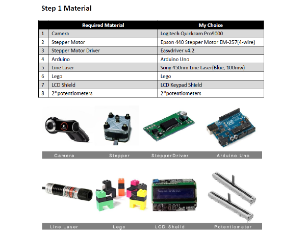
Step 1 Material
Note: For the camera, In most cases, DAVID works in lowlight conditions to get a clear contrasted laser line. So the cam should be able to handle this. High light sensitivity and as little noise as possible is recommended. For the laser line, laser line should be as thin as possible –> focusable; as bright as possible; perfect straight line and a red or green laser if you use a color camera.
Step 2 Software Installation
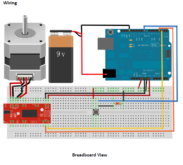
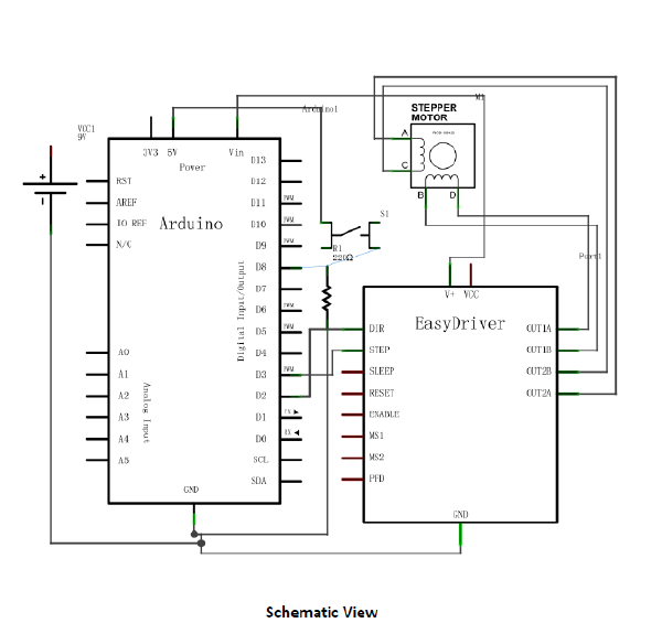
Download the latest free David Laser Scanner in the David official site. Or open the local installation for David Laser Scanner V3.1. Find the documentation of the David software as well as many useful tips. Note: Limitation of the free David Laser Scanner is that the maximum resolution of the capture can be used by software is up to 640*480 even if the camera can capture with a HD resolution (1920*1200) , while the full license version can use as much as your camera can offer. 329 EUR for the full license and one can achieves super precise result with this reasonable price. David Laser Scanner is windows platform only. Step 3 Control A Stepper Motor With a stepper motor driver, we can let the movement of a stepper motor slower, smoother and quieter than controlling it with Arduino directly.
Find the Arduino code here.
Note: 9V external power supply is necessary for driving a stepper. The USB power supply is not sufficient since it has a current limit. Do please turn off the power supply, if you want to exchange the connection of the 4 pins of the stepper. Or it may damage your circuit because it may generate an inverse voltage. Micro step can let the stepper slower and also quieter, but it is less accurate compared with a full step. With the easyDriver, you have options of 1/2, 1/4, 1/8 micro step. By default the easyDriver will drive a stepper with 1/8 micro step. And it can be altered by setting the MS1 and MS2 Pin High and Low. The documentation of easyDriver can be found and you can find the datasheet (here).
Step 4 Building the Gears
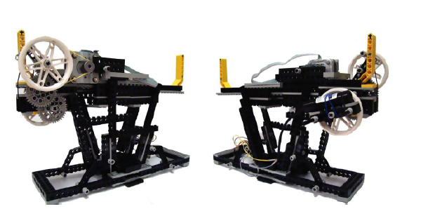
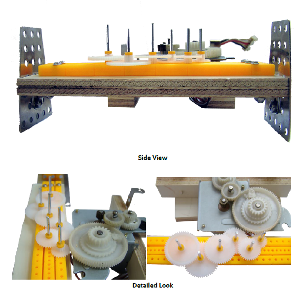
Use the gears of the Lego parts. The detailed pictures showed below.
<videoflash type=vimeo>42917722</videoflash>
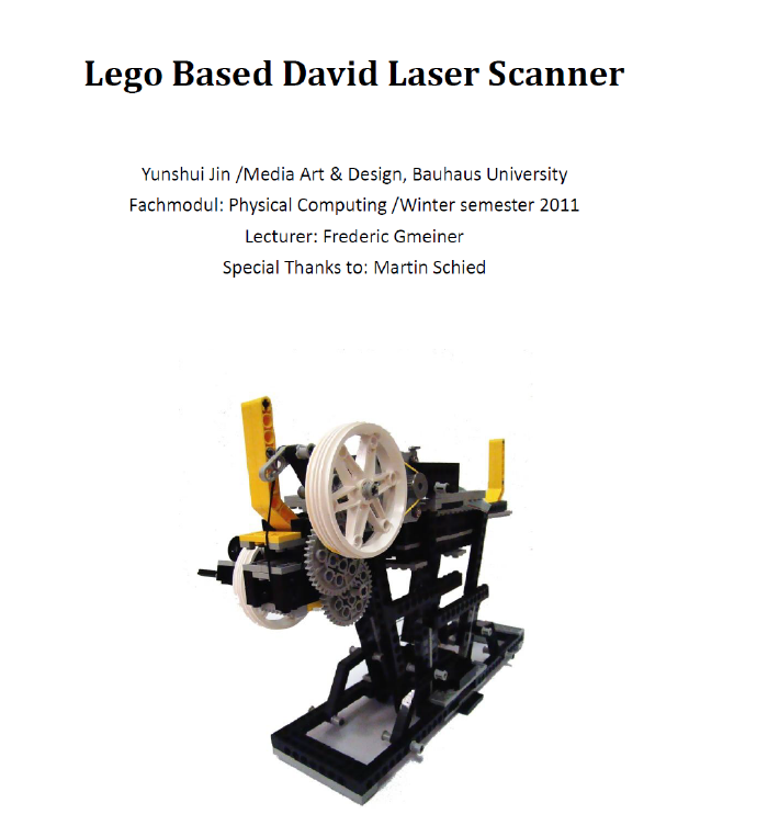
The purpose of building up gears is to slow down the movement of laser. One can assemble the right gears to achieve a high gear ratio. The higher the ratio is, the better quality will be, especially when you want to achieve very precise result with a HD camera and the commercial version of David.
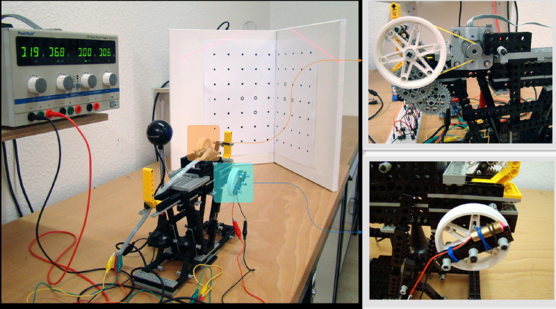
Use the yellow belt to connect the stepper motor with the main wheel which drives the gear set and attach the line laser to the wheel which is the “end” of the gear set at the other side. The function of the Lego frame is to fix the stepper motor and stabilize the whole set. Or you can build up with “professional” gears.
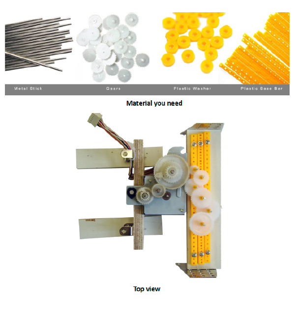
The above picture is showing what I achieved with these gears, and I bought the initial material online. Here is the initial material (available in China only) : plastic gears, metal stick, plastic base bar, plastic washer. In the right picture of the “detailed look”, the gear stays at most left side is the last gear of the whole gears chain.
Note: Since the material of plastic is quiet elastic, the Lego based scanner is kind of loose and the belt connecting the stepper with the wheel also brings some problem like sliding issues. It would be much better if you can build the “professional” one. However, you need to gain some experience with the mechanical tools and the “professional” gears are not so easy to find, unless you build your own with laser cutter or 3D printer.
Step 5 Coding & Wiring
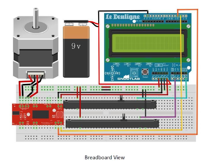
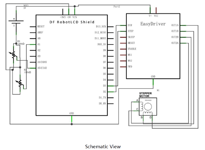
Wiring Plug the DFRobot LCD shield into the Arduino, and follow the schematic below. Begin with the circuit of the stepper done in the previous steps. Add more components to the circuit like potentiometers and LCD shield to build up the hardware interface so that you can adjust the motor speed and the rotation range by these two potentiometers directly.
Coding: Install the library (LCD shield Library)for the LCD shield ( detailed installation steps can be found in the “READ ME”). And also writing the function of if receive the ‘S’ from the serial port.
Notice that the switcher for triggering the stepper is removed from the circuit. David software will send ‘S’ through the serial port when the start button is clicked, and ‘T’ will be sent if the stop button is clicked. In order to synchronize the software with the hardware, a function of triggering the stepper by receiving ‘S’ and ‘T’ is written in the code. Complete code with very detailed comments can be found here.
Step 6 Camera calibration
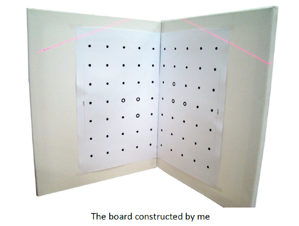
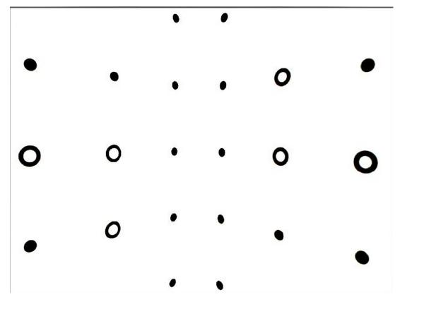
Make the calibration board, which has two perpendicular wood boards with the right pattern. The calibration pattern to be printed out for the board can be found here].
Connect the camera and Arduino to computer, and launch the David software.
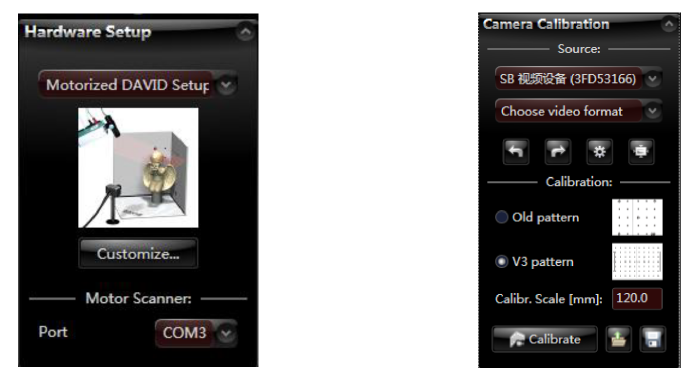
Use the right settings for the David:
Please adjust the camera settings; the picture captured by camera should be as bright as possible while the black dot on the calibration board can still be clearly recognized. Like the picture showed below.
Click the “Calibrate” button to finish calibration. Notice that once you finish the calibration, the position of the camera can’t be changed anymore.
Step 7 First scan
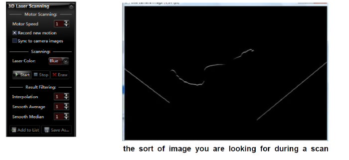
Now everything is ready. We could start our first scan. Do remember to check the “Record new motion “option. One important thing is you need to re-adjust the camera setting, unlike the calibration picture, now you need to achieve a picture as black as possible while only the laser line could be easily recognized ,and you can also adjust the laser focus to make it as thin as possible. Like the picture showed below.
Step 8
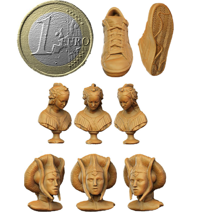
Once you finish the first scan. We can do the repetition scan. Just make sure the relative position of the laser and the camera is fixed and we can remove the calibration board to scan anything we want. We now finish the mobile laser scanner. Here is some demo scan result from the official David site (from the commercial version) .
