No edit summary |
mNo edit summary |
||
| (12 intermediate revisions by 2 users not shown) | |||
| Line 1: | Line 1: | ||
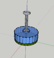
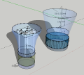
This tutorial is about how i build my DIY-Microscope using this webcam. In the very beginning I was very curious how it would work out to print it with the 3D-printer. This is my sketchup-sketch for it: | |||
<gallery> | |||
File:3d draft 121125.png| | |||
File:3d draft 121125 2.png| | |||
File:3d draft 121126.png| | |||
</gallery> | |||
[[ | [[Media:microscopy ch.zip|Download SketchUp Files]] | ||
Unfortunately the 3D-printer got damaged by someone, when i started to work. So i decided to work with materials that i can find in every hardware store. I made up my mind how the mechanism is supposed to work to adjust the camera‘s focus and how it can have a fixed stand. In class we developed the idea with the screw and the nut. I really liked that mechanism because it reminded me on the gluestick-mechanism. So i gave it a try. | |||
<gallery> | |||
File:DSC02234 2.jpg| | |||
File:Scannen 4 2.jpg| | |||
File:Scannen 2 22.png| | |||
File:Scannen 6 2.jpg| | |||
File:Scannen 7 2.jpg| | |||
File:Scannen 8 2.jpg| | |||
</gallery> | |||
As you can see in my sketches, the difficulty i came up with, is about having a rotating wheel, that includes the nut and rotates in a fixed position, while pushing the screw upwards and with it the camera. My construction wants to have the rotating wheel setable from every hand-position so it is not thinkable to cover it from the top to the bottom part, because the covering would interfere with a smooth hand-movement. That means, the connection from top to bottom must proceed inside the whole construction. So i have two main-construction parts. Top-to-bottom-part (1st) and Rotate-and-Push-part (2nd). | |||
At the very top, the camera needs to be able to move over the top and under it. So it is possible to get the closest position to the petri dish. And also to get some more distance to it than necessary. | |||
Furthermore the camera needs to be inside the top-part, while the 2nd part, that includes the camera needs to be outside the 1st part. That creates a little confusion. | |||
To fix that, I devide the 2nd part into 2 pieces. The one that holds the camera (2a) and is inside the top-part, and the second that is the rotating wheel (2b), lose-fixed in vertical-position, while still able to rotate free, pushing 2a with the help of a screw-nut-situation. So it is rather screwing the camera-part to the top. This camera-part is being hold in position with thin sticks that go through the top-part. These sticks also need to be movable through the top-part, because they are tied to the camera part on the upper side und tied to a nut on the bottom side. That gives the connection from the outside-rotating wheel and the inside-camera-part. The nut is connected to a screw that is inside the rotating wheel-part. | |||
< | My Top-to-bottom stable part needs to have a stopper where the rotating wheel hangs in to move freely. There should be as less free space as possible between the 1st and the 2nd part, reasoning in a smooth focus movement that is required. | ||
SO ALL MOVING PARTS MUST BE AS TIGHT TOGETHER AS POSSIBLE. | |||
All parts I used I found in different areas of a hardware store. These are: | |||
* screws | |||
* nuts | |||
* screw-connector | |||
* candle | |||
* bulb fitting | |||
* tape | |||
* rubber-isolation-tools | |||
* shim | |||
* piece of easy-to-cut-plastic from anything | |||
<gallery> | |||
File:Uebersicht.jpg| | |||
File:DSC02208 2.jpg| | |||
File:DSC02249 2.jpg| | |||
File:DSC02240 2.jpg| | |||
File:DSC02241 2.jpg| | |||
File:Scsh 121217.jpg| | |||
</gallery> | |||
The microscope is unfortunately not working that proper as i would like it to. The problem is that the free spaces are giving too much play. It is possible to adjust the focus of the camera, but not as smooth as i think it should be. | |||
Furthermore i wasnt aware that the sensor of the camera is very sensitive for friction and dust, so the quality of my image is full of noise. One should be really careful in turning and fixing the lense. | |||
Latest revision as of 17:28, 16 May 2013
This tutorial is about how i build my DIY-Microscope using this webcam. In the very beginning I was very curious how it would work out to print it with the 3D-printer. This is my sketchup-sketch for it:
Unfortunately the 3D-printer got damaged by someone, when i started to work. So i decided to work with materials that i can find in every hardware store. I made up my mind how the mechanism is supposed to work to adjust the camera‘s focus and how it can have a fixed stand. In class we developed the idea with the screw and the nut. I really liked that mechanism because it reminded me on the gluestick-mechanism. So i gave it a try.
As you can see in my sketches, the difficulty i came up with, is about having a rotating wheel, that includes the nut and rotates in a fixed position, while pushing the screw upwards and with it the camera. My construction wants to have the rotating wheel setable from every hand-position so it is not thinkable to cover it from the top to the bottom part, because the covering would interfere with a smooth hand-movement. That means, the connection from top to bottom must proceed inside the whole construction. So i have two main-construction parts. Top-to-bottom-part (1st) and Rotate-and-Push-part (2nd).
At the very top, the camera needs to be able to move over the top and under it. So it is possible to get the closest position to the petri dish. And also to get some more distance to it than necessary. Furthermore the camera needs to be inside the top-part, while the 2nd part, that includes the camera needs to be outside the 1st part. That creates a little confusion. To fix that, I devide the 2nd part into 2 pieces. The one that holds the camera (2a) and is inside the top-part, and the second that is the rotating wheel (2b), lose-fixed in vertical-position, while still able to rotate free, pushing 2a with the help of a screw-nut-situation. So it is rather screwing the camera-part to the top. This camera-part is being hold in position with thin sticks that go through the top-part. These sticks also need to be movable through the top-part, because they are tied to the camera part on the upper side und tied to a nut on the bottom side. That gives the connection from the outside-rotating wheel and the inside-camera-part. The nut is connected to a screw that is inside the rotating wheel-part. My Top-to-bottom stable part needs to have a stopper where the rotating wheel hangs in to move freely. There should be as less free space as possible between the 1st and the 2nd part, reasoning in a smooth focus movement that is required. SO ALL MOVING PARTS MUST BE AS TIGHT TOGETHER AS POSSIBLE.
All parts I used I found in different areas of a hardware store. These are:
- screws
- nuts
- screw-connector
- candle
- bulb fitting
- tape
- rubber-isolation-tools
- shim
- piece of easy-to-cut-plastic from anything
The microscope is unfortunately not working that proper as i would like it to. The problem is that the free spaces are giving too much play. It is possible to adjust the focus of the camera, but not as smooth as i think it should be. Furthermore i wasnt aware that the sensor of the camera is very sensitive for friction and dust, so the quality of my image is full of noise. One should be really careful in turning and fixing the lense.


