No edit summary |
No edit summary |
||
| (13 intermediate revisions by the same user not shown) | |||
| Line 1: | Line 1: | ||
[[File:First.jpg]] | ===Phase I=== | ||
[[File:Second.jpg]] | |||
[[File:Third.jpg]] | :<tt>Learning process, getting to know electronics and basic concepts about electric circuits | ||
[[File:Forth.jpg]] | :the logic, and how to draw them.</tt> | ||
::[[File:First.jpg|200px]] [[File:Second.jpg|200px]] [[File:Third.jpg|200px]] | |||
::[[File:Forth.jpg|200px]] [[File:Fifth.jpg|200px]] [[File:Sixth.jpg|200px]] | |||
::Bread boards, resistors, capacitors, relays, switches, 555 Timer ..etc | |||
---- | |||
===Phase II=== | |||
:<tt>Designing an experiment, using the concepts of either: | |||
:* Variable resistance | |||
:* Trigger Switch </tt> | |||
::[[File:Exp1.jpg|200px]] [[File:Exp2.jpg|200px]] [[File:Exp3.jpg|200px]] | |||
::When using liquid -water- as a conductor, and having poles connected to the circuit fixed in the | |||
:: liquid pool, the change of the liquid level results in change of resistance. | |||
::[[File:Exp4.jpg|200px]] [[File:Exp5.jpg|200px]] [[File:Alive1.jpg|200px]] | |||
::Switching from the a motor mechanical way of changing the water level, to a more natural way. | |||
::using the force of air blowing, breathing, to change the water levels as shown in the sketch. | |||
::and thus changing the resistance! | |||
::[[File:Alive2.jpg|200px]] [[File:Alive3.jpg|200px]] [[File:Add1.jpg|200px]] | |||
---- | |||
===Phase III=== | |||
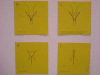
:Developing the initial experiment. In this case, new features were added to the home made instrument. | |||
:Three extra "keys" -switches- were added to the design.Wiered to three extra 555 timers, | |||
:the keys decide which timers are connected and which are not.Resulting in a change in the output sound. | |||
::[[File:2sketch1.jpg|200px]] [[File:2sketch2.jpg|200px]] [[File:2in1.jpg|200px]] | |||
::[[File:IMG_0233.JPG|200px]] [[File:IMG_0234.JPG|200px]] [[File:IMG_0235.JPG|200px]] | |||
::[[File:IMG_0240.JPG|200px]] [[File:IMG_0241.JPG|200px]] [[File:IMG_0243.JPG|200px]] | |||
---- | |||
====the exhibition :==== | |||
===Electric Trumpet=== | |||
:Exhibited in the summery works of the Bauhaus2014. | |||
::[[File:Plates1.JPG|200px]] [[File:IMG_6298.JPG|200px]] [[File:IMG_0249.JPG|200px]] | |||
---- | |||
::<videoflash type=vimeo>100918927</videoflash> | |||
Latest revision as of 17:54, 16 July 2014
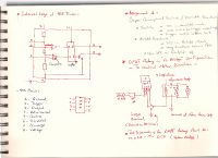
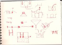
Phase I
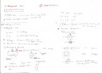
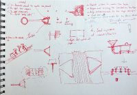
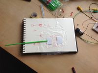
- Learning process, getting to know electronics and basic concepts about electric circuits
- the logic, and how to draw them.
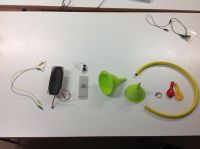
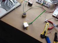
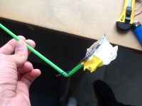
- Bread boards, resistors, capacitors, relays, switches, 555 Timer ..etc
Phase II
- Designing an experiment, using the concepts of either:
- Variable resistance
- Trigger Switch
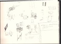
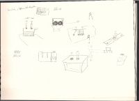
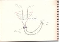
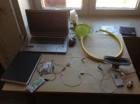
- When using liquid -water- as a conductor, and having poles connected to the circuit fixed in the
- liquid pool, the change of the liquid level results in change of resistance.
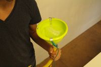
- Switching from the a motor mechanical way of changing the water level, to a more natural way.
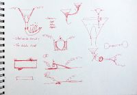
- using the force of air blowing, breathing, to change the water levels as shown in the sketch.
- and thus changing the resistance!
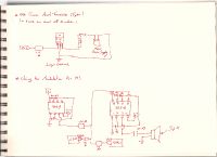
Phase III
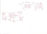
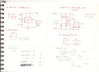
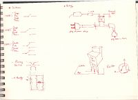
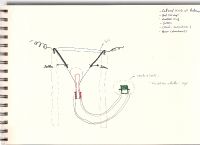
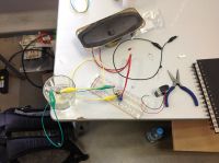
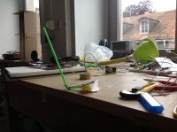
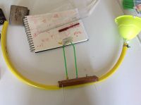
- Developing the initial experiment. In this case, new features were added to the home made instrument.
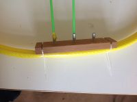
- Three extra "keys" -switches- were added to the design.Wiered to three extra 555 timers,
- the keys decide which timers are connected and which are not.Resulting in a change in the output sound.
the exhibition :
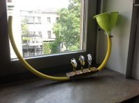
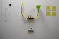
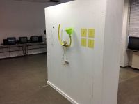
Electric Trumpet
- Exhibited in the summery works of the Bauhaus2014.
- <videoflash type=vimeo>100918927</videoflash>
