No edit summary |
No edit summary |
||
| Line 141: | Line 141: | ||
and light gate for control of motor movement.<br><br> | and light gate for control of motor movement.<br><br> | ||
[[File: | [[File:HbridgeSwitches.jpg]]<br> | ||
Experimenting with two switches (H-bridge) for the horizontal | Experimenting with two switches (H-bridge) for the horizontal | ||
movement of the DC motor.<br><br> | movement of the DC motor.<br><br> | ||
[[File: | [[File:FirstDraw.jpg]]<br> | ||
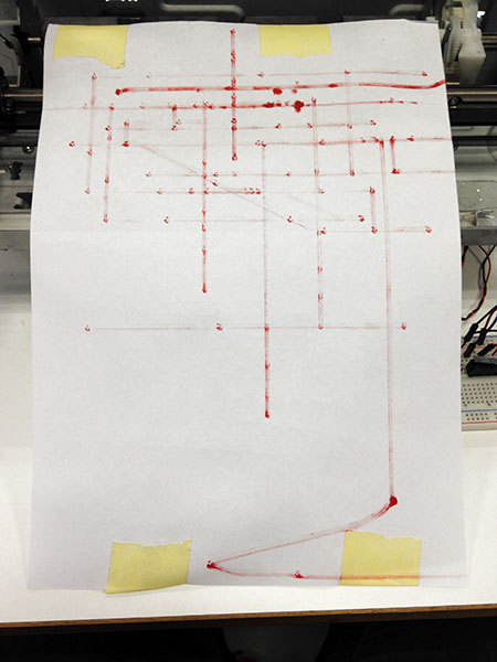
First results..<br><br> | |||
[[File: | [[File:Reexsketch.jpg]]<br> | ||
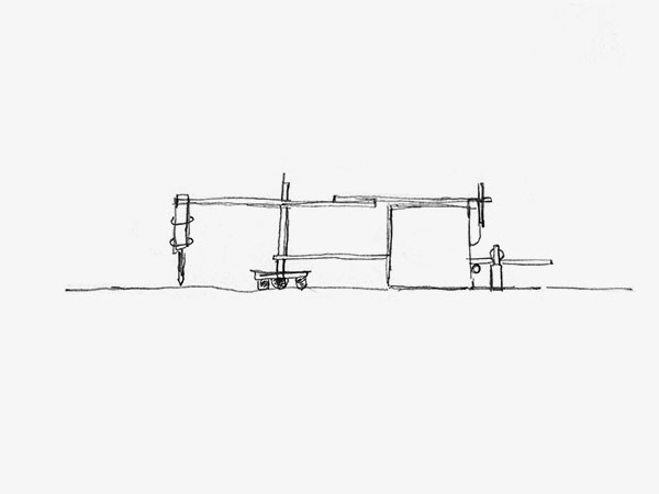
Idea: A movable „arm“ that allows going back, forth, left and right (movement in x and y direction) with a changeable „nose“.<br> Make the printers inner movements visible outside of the casing.<br><br> | |||
[[File:MazeSchematic.jpg]]<br> | [[File:MazeSchematic.jpg]]<br> | ||
Revision as of 17:11, 15 December 2015
The Improbable Switch
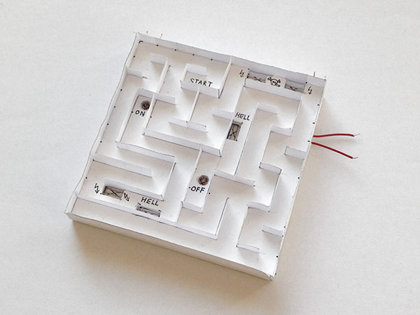
The Improbable Switch, maze module
For the first assignment I built a switch that needs a (playful) effort to be operated.
It should stretch the time between the different states of change - and it should be allowed to „revolt".
I decided to design a little maze.
In the beginning two little metal balls are positioned at the starting point of the maze.
By that time no current flows through the circuit.
The goal is to make one of the balls fall into the „on-hole“ before the other ball reaches the „off-hole“.
The game is over as soon as one of the balls gets trapped in „hell“.
By activating the „on-hole“ a heart beat sound is turned on.
This sound continues until it is turned off by reaching the „off-hole“.
A loud noise starts buzzing for three seconds when one of the balls is trapped in „hell“.
For a restart both balls need to be removed and the reset-button on the circuit board is to be pushed.
WORK IN PROGRESS
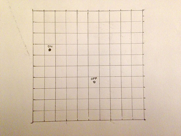
Sketch for the frame of the maze (10 cm x 10 cm).
Each corridor should have a width of at least 1 cm.
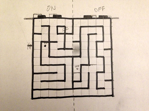
Final sketch for the two dimesnional structure of the maze.
Defining pins for connecting the „on“ / „off“ circuit.
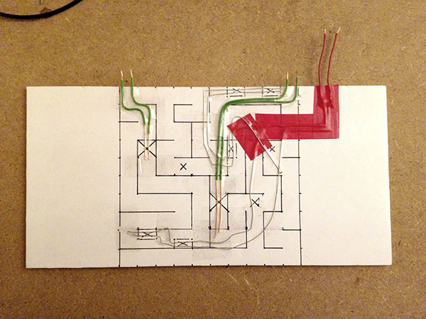
Setting up the switch structure with wire and tape.
Adding a connection for the „hell“ - circuit (red).
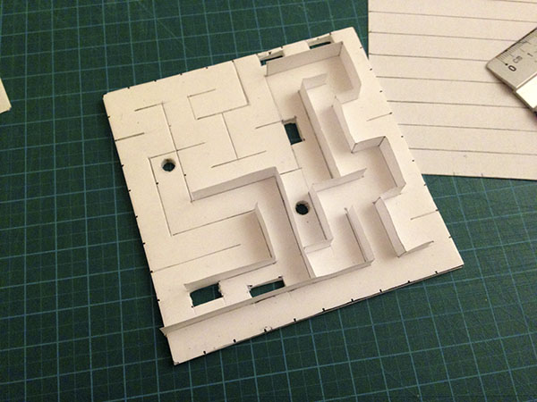
Building the three dimensional wall structure of the maze.
The paper walls are jammed into the sliced Kappafix.
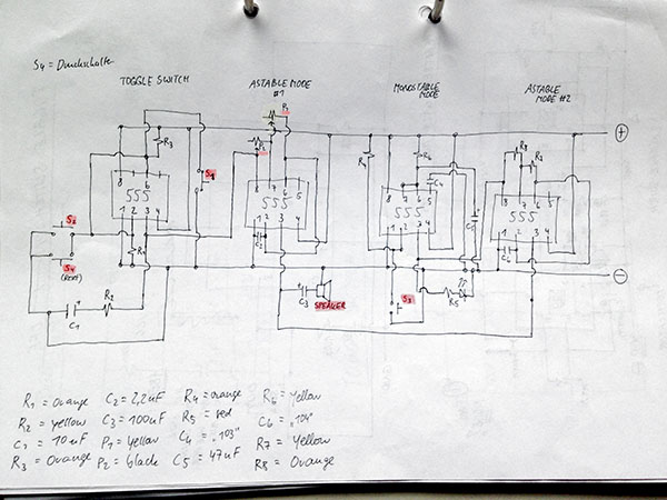
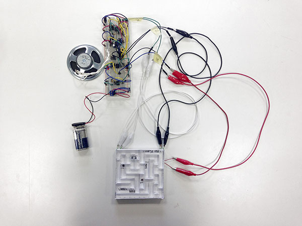
Schematic for the electronics with four 555 Timers:
- monostable mode (trigger) for „on“ and „off“
- astable mode for heart beat sound
- monostable mode (trigger) for „hell“ sound
- astable mode for „hell“ sound (using the same speaker)
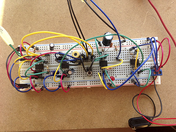
Circuit borad with reset switch.
RESULT
Variable Resistance
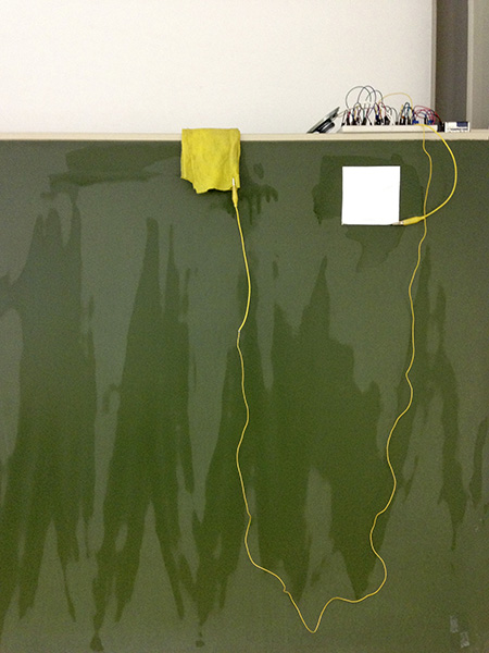
Variable Resistance, modified chalk board
The biggest challenge of Variable Resistance was to find materials that are flexible in terms of the current flowing though them.
We tested things by including them into the circuit of a 555 timers astable mode.
After trying out things that I carried to the classroom I had the idea to connect something to the circuit that was already there.
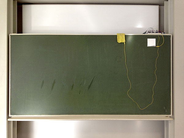
The chalk board was a good example: by connecting a humid rag (to pin 6) and a piece of wet aluminium foil sticking to the board (to pin 7) I could draw sounds by wiping the surface.
Thereby I found out that it is very important to „calibrate“ the used material: a very high and still hearable tone should sound when the rag is put directly onto the aluminium connector.
By moving the rag further away, the tone will become deeper and deeper (as the resistance rises).
This tone range can be adjusted by turning a potentiometer (between pin 7 and 8) and by trying out different capacitors (between pin 1 and 2).
WORK IN PROGRESS
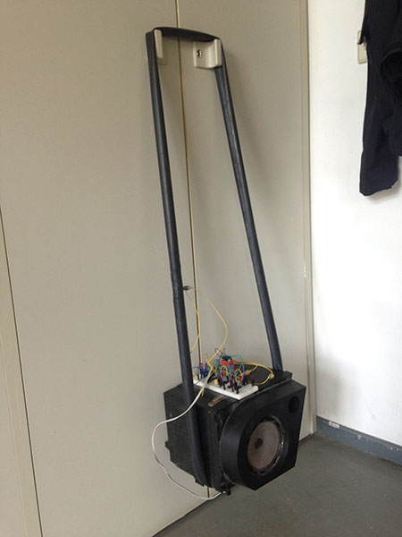
Trying out a bicycle tire filled with water and wire as a variable resistor for a 555 Timer astable mode.
(failed)
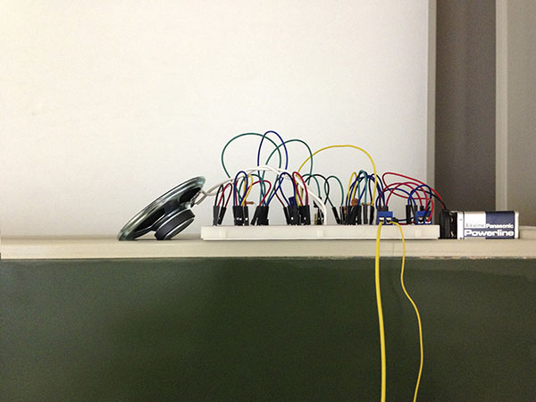
Circuit board with 555 Timer astable mode and speaker on top of the chalk board..
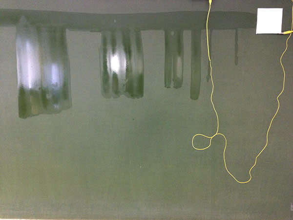
Connecting one side of the resistor to the chalk board via aluminium foil.
The foil sticks automatically to the wet spots on the board.
A sponge was used to draw temporary traces that conduct electricity and therefore can function as parts of the resistor.
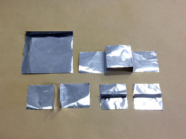
Squares and rectangles of aluminium foil with parallels to different electrical parts.
They can be included in the chalk board circuit.
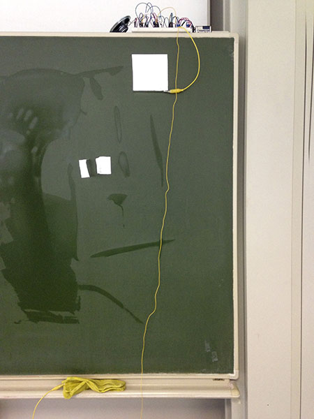
Testing aluminium parts in the circuit.
RESULT
Final Work: The Reexperiventer
Manual:
1. Select an image you want to reexperivent (online, in a book, in a magazine, …)
2. Print it out (7 cm width max.) and put it underneath the tip of the pen so that it is located at the pictures center.
3. Cover the image with a sheet of transparent paper.
4. If you chose a totalitarian, evil, dangerous or seemingly untouchable image: put on rubber gloves.
5. Check out the switches and their effects on the movement of the device.
6. Rotate the device to the starting position. Move down the pen until it touches the paper.
7. Take a deep breath and start drawing.
8. Once you finished every line of the image move the device to the very right or left.
9. Enjoy the moment and appreciate to be human.
WORK IN PROGRESS
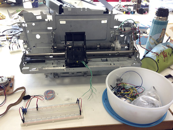
Salvaged printer parts:
A metal case, rails, transport systems for paper and printer head, two DC motors
and light gate for control of motor movement.
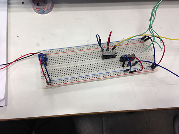
Experimenting with two switches (H-bridge) for the horizontal
movement of the DC motor.
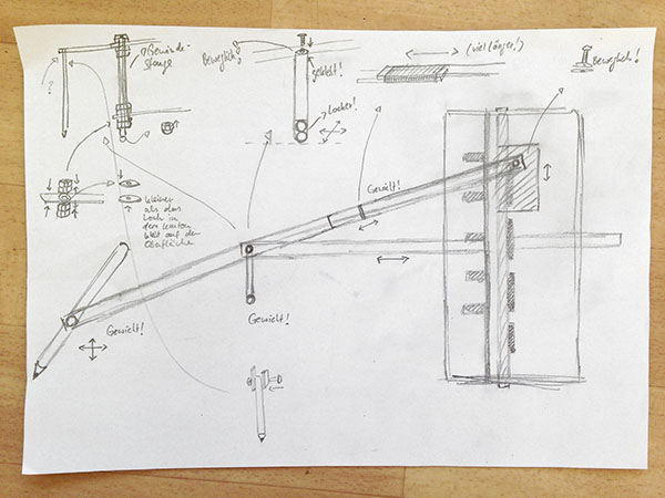
Idea: A movable „arm“ that allows going back, forth, left and right (movement in x and y direction) with a changeable „nose“.
Make the printers inner movements visible outside of the casing.

Schematic for the electronics with four 555 Timers:
- monostable mode (trigger) for „on“ and „off“
- astable mode for heart beat sound
- monostable mode (trigger) for „hell“ sound
- astable mode for „hell“ sound (using the same speaker)

Circuit borad with reset switch.
RESULT
