GMU:Bioelectronics, aesthetics and other interesting things/PhyChip synthesiser: Difference between revisions
| Line 2: | Line 2: | ||
<gallery> | <gallery> | ||
image:phychip-synthesiser.png|PhyChip Synthesiser | image:phychip-synthesiser.png|PhyChip Synthesiser | ||
image:circadia-vco-8-steps-module.png|circadie module | |||
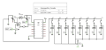
image:bioscilator.png|bioscilator modul | image:bioscilator.png|bioscilator modul | ||
image:hex-schmitt-trigger.png|Hex Schmitt trigger | image:hex-schmitt-trigger.png|Hex Schmitt trigger | ||
</gallery> | </gallery> | ||
In electronics, a Schmitt trigger is a comparator circuit with hysteresis implemented by applying positive feedback to the noninverting input of a comparator or differential amplifier. It is an active circuit which converts an analog input signal to a digital output signal. The circuit is named a "trigger" because the output retains its value until the input changes sufficiently to trigger a change. | |||
== Physarum plates == | == Physarum plates == | ||
Revision as of 22:05, 6 June 2016
PhyChip Synthesiser

PhyChip Synthesiser
circadie module

bioscilator modul

Hex Schmitt trigger


In electronics, a Schmitt trigger is a comparator circuit with hysteresis implemented by applying positive feedback to the noninverting input of a comparator or differential amplifier. It is an active circuit which converts an analog input signal to a digital output signal. The circuit is named a "trigger" because the output retains its value until the input changes sufficiently to trigger a change.
Physarum plates
Utilised coated 35 mm petri dishes in a 3 row x 2 column arrangement. Every plate was treated with an aluminium mesh with a resistance of 0.5 Ω-cm. The mesh is separated by the plate walls. In front of each cell a 4 x 3 mm aluminium finger was placed to create the contact areas. Physarum resistance was around 1300-1500 Ω·cm. On top of each plate added a 3 mm agar 2% concentration for placing the physarum.

Petri dish with 6 plates

Distribution of the physarum network early stage

Distribution of the physarum network final stage


