No edit summary |
No edit summary |
||
| (32 intermediate revisions by the same user not shown) | |||
| Line 1: | Line 1: | ||
<br> | |||
== Application Sketch == | |||
<br> | |||
[[File:Application_thread_11.jpg]] | |||
<br> | <br> | ||
== Thread Geometries == | == Thread Geometries == | ||
| Line 19: | Line 26: | ||
- a transparent plastic bowl <br> | - a transparent plastic bowl <br> | ||
- thread<br><br> | - thread<br><br> | ||
[[File:Aufbau_Thread1_1.png]]<br><br> | |||
[[File:Aufbau_Thread1_2.png]]<br><br> | |||
[[File:Aufbau_Thread1_3.png]]<br><br> | |||
How to use it:<br><br> | How to use it:<br><br> | ||
| Line 25: | Line 36: | ||
3. Connect the LED, the button battery and the clamp<br> | 3. Connect the LED, the button battery and the clamp<br> | ||
4. Put the plastic bowl above the installation and put the magnets in place<br> | 4. Put the plastic bowl above the installation and put the magnets in place<br> | ||
5. Set up the camera, darken the room, trigger the | 5. Set up the camera, darken the room, push the trigger and move the upper magnet!<br> | ||
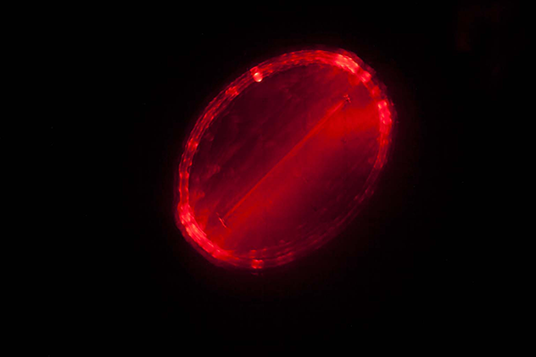
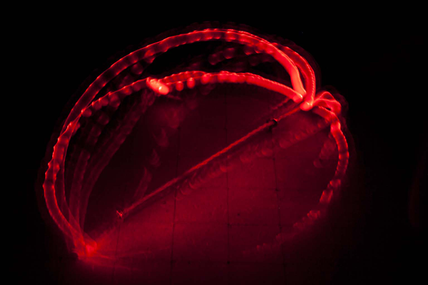
[[File:Licht_Thread1_1.png]]<br><br> | |||
[[File:Licht_Thread1_2.png]]<br><br> | |||
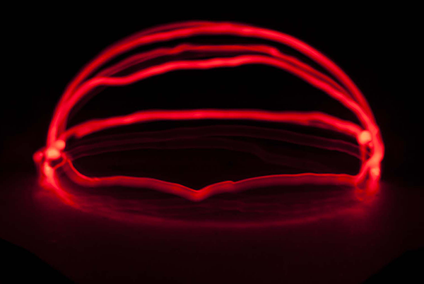
[[File:Licht_Thread1_3.png]]<br> | |||
<br> | |||
== Computation and Communication with Knots == | |||
<br> | |||
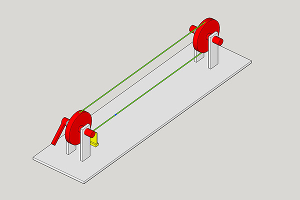
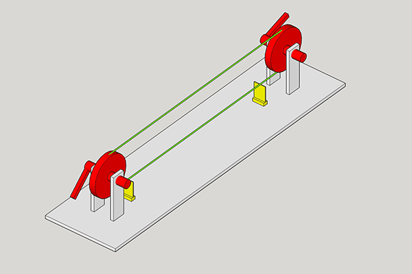
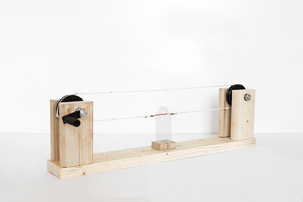
This "machine" is capable of two things: <br> | |||
- it can help the user to conduct simple (and complex - if developed further) calculations and <br> | |||
- it can be used as a communication tool for two people by translating messages in a kind of morse code<br><br> | |||
Components: | |||
- Wood (left overs) <br> | |||
- two pieces of threaded rod <br> | |||
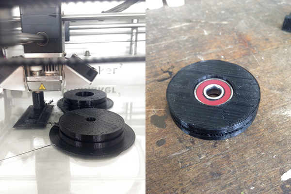
- two 3D printed wheels <br> | |||
- a ball bearing that fits to the threaded rod<br> | |||
- and thread<br><br> | |||
[[File:3D_knots1.jpg]]<br><br> | |||
[[File:3D_knots2.jpg]]<br><br> | |||
[[File:3D_knots_print.png]]<br><br> | |||
How to use it:<br><br> | |||
1. Use the winder to make the knots scratch the thin plastic plate <br> | |||
2. Wind the thread until the red section crosses the thin plastic plate <br> | |||
3. Move the winder forward to add "knot-scratches" <br> | |||
4. Move the winder backward to subtract "knot-scratches" <br> | |||
5. Enter your calculation <br> | |||
6. Wind back to the red mark and count the "scratches"- <br> | |||
they represent the result of your calculation!<br><br> | |||
[[File:Knot_Calculator.png]]<br> | |||
<br> | |||
== Braiding == | |||
<br> | |||
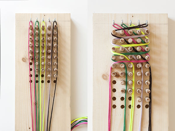
This "braiding board" is an experimenting platform for different braiding techniques.<br> | |||
Its level of complexity can be modified by changing different parameters. <br> | |||
It consists of five "thread ports"and "thread gaps", forty interchangeable "spacers"and fifty "spacer slots". <br> | |||
<br><br> | |||
Components: | |||
- Wood (left over) <br> | |||
- five pieces of thread <br> | |||
- forty wooden dowels <br> | |||
- and five screwable rings <br><br> | |||
[[File:thread_cont_board.jpg]]<br><br> | |||
How to use it:<br><br> | |||
1. Define your setting: plug the spacers in / out <br> | |||
2. Insert each thread into a ring <br> | |||
3. Think of an algorithm / a braiding technique / your experiment <br> | |||
4. Note: the order of the threads in the "clipboard" (bottom of the board) makes a big difference <br> | |||
5. Start braiding! <br><br> | |||
Some first experiments:<br> | |||
[[File:thread_knots_complex.jpg]]<br> | |||
Producing knots<br><br> | |||
[[File:thread_linedup.jpg]]<br> | |||
Coincidental synchronization-algorithm: all threads end up in the same place<br><br> | |||
[[File:thread_complex.jpg]]<br> | |||
Complexity + knots by following the "clipboard" order and a simple algorithm: left, right, ...<br> | |||
<br> | |||
== Networks == | |||
<br> | |||
How can we visualize or encode networks in a different way than we are used to ?<br><br> | |||
This sketch is a proposal to transform networks and their different parameters by shaping braids / thread patterns. <br> | |||
It is not predictable that random braid configurations evolve into proper braid structures that can exist without any outer support.<br> | |||
Therefore the "machine" above ("braiding") shall be used to set up a thread-path that does not fall apart easily.<br><br> | |||
The structure of the transformation is defined by several parameters that represent different properties of the network.<br><br> | |||
Example:<br> | |||
- the network could visualize trading routes between cities<br> | |||
- the colors could then represent different goods, for instance: yellow = red pedal boats<br> | |||
- A,B,C and D represent the nodes of the network. In this case they could represent the cities.<br> | |||
- the amount of goods can be represented by the location of a color inside the four squares of A,B,.. counted from left to right.<br> If the second square of A is yellow than this could mean that city A has 200 paddle boats.<br> | |||
- now, a match of the colors AND the locations of the colors inside of A,B,C or D means that those two or more cities (nodes) exchange goods (are connected).<br> | |||
In this example: A and B's second squares are yellow -> those two cities trade 200 paddle boats.<br> | |||
- if there is no match then there is no connection.<br><br> | |||
The "braids" and the network drawings can be infinitely translated into each other.<br><br> | |||
[[File:Network_colorstrings.jpg]]<br> | |||
<br> | |||
== Levers and Cranes == | |||
<br> | |||
How can we move something in every three dimensional direction? <br><br> | |||
A mechanical feature of thread is that it can pull - but it can't push. <br> | |||
This structure helps to move things with thread by the use of additional mechanical support.<br> | |||
It is meant to be used by two peoples who operate two strings (yellow, each person) in order to move the object.<br><br> | |||
One important part of that structure is a spring (green). <br> | |||
It is attached to a fixed spot in the room. It stretches and contracts itself when the attached object is moved 1) parallel to the ground and 2) up and down. <br><br> | |||
Another essential aspect is the thread that goes through / is attached to the middle of the object. <br> | |||
It holds the object in place so that a precise movement is assured.<br> | |||
It also takes away some of the objects weight in order to exonerate the operator strings.<br><br> | |||
A third important part are the structures that attach the "middle-thread" (red) to the ceiling and the ground.<br> | |||
They 1) hold the middle-thread in place, they 2) react to the operators movements by turning in the required direction (blue wheel) and they 3) provide a bracket for the spring.<br> | |||
[[File:Kran_thread.png]]<br><br> | |||
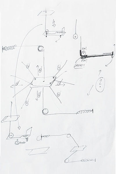
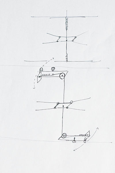
Sketches and previous versions:<br> | |||
[[File:3Dplate_sketchpaper1.jpg]] | |||
[[File:3Dplate_sketchpaper1_1.jpg]]<br> | |||
[[File:3Dplate_sketchpaper3_1.jpg]] | |||
[[File:3Dplate_sketchpaper3.jpg]] | |||
<br><br> | |||
<br> | |||
== Pulleys == | |||
<br> | |||
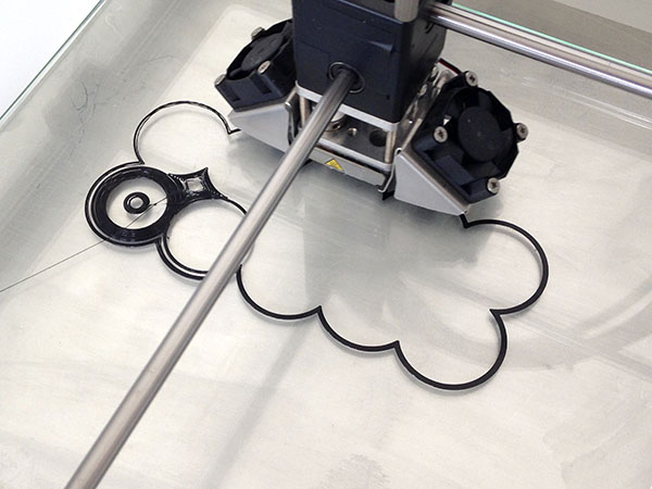
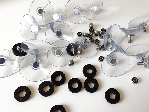
This is an assembly kit that allows to work with pulley/thread constructions in a flexible way. <br> | |||
It works best with flat and smooth surfaces and it can be used in vertical and horizontal constructions<br> (such as logical operations, see Rachel Smith's and + or gates).<br> | |||
The parts:<br> | |||
1) 3D printed pulley wheels <br> | |||
2) metal ball bearings <br> | |||
3) plastic suction pads and <br> | |||
4) thread. | |||
<br><br> | |||
[[File:3Dprint_pulley.jpg]]<br><br> | |||
[[File:pulleykit.jpg]] <br><br><br> | |||
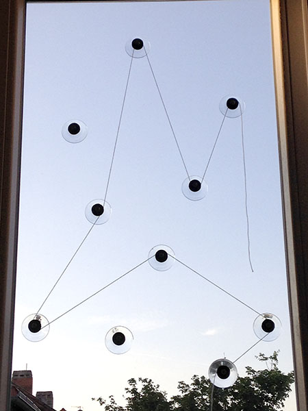
First window construction: | |||
[[File:pulley_window.jpg]]<br> | |||
<br><br> | |||
Latest revision as of 09:50, 28 June 2016
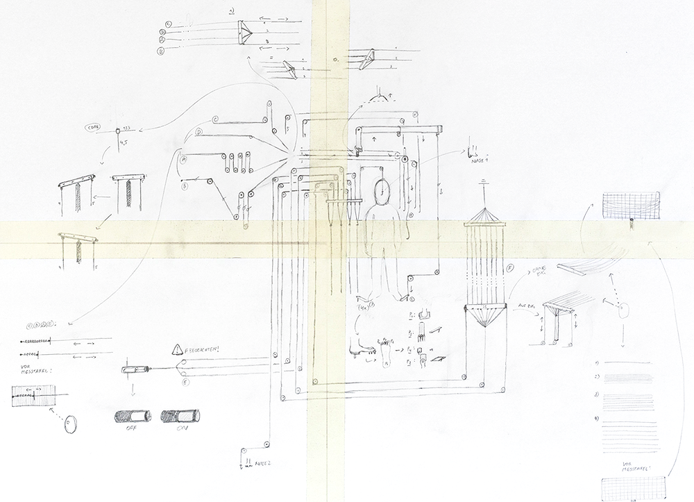
Application Sketch
Thread Geometries
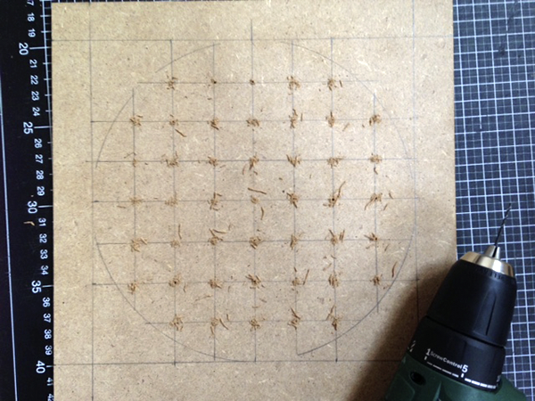
This is the starting point for a kit that allows to visualize geometric forms by using thread (along with some other things).
Components:
- camera with "B" mode
- tripod
- wooden plate
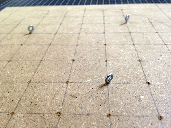
- some screwable hooks
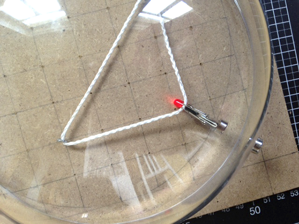
- LED
- button battery
- piece of paper
- clamp
- two magnets
- a transparent plastic bowl
- thread
How to use it:
1. Screw in as many hooks as you like
2. Insert a certain length of thread
3. Connect the LED, the button battery and the clamp
4. Put the plastic bowl above the installation and put the magnets in place
5. Set up the camera, darken the room, push the trigger and move the upper magnet!
Computation and Communication with Knots
This "machine" is capable of two things:
- it can help the user to conduct simple (and complex - if developed further) calculations and
- it can be used as a communication tool for two people by translating messages in a kind of morse code
Components:
- Wood (left overs)
- two pieces of threaded rod
- two 3D printed wheels
- a ball bearing that fits to the threaded rod
- and thread
How to use it:
1. Use the winder to make the knots scratch the thin plastic plate
2. Wind the thread until the red section crosses the thin plastic plate
3. Move the winder forward to add "knot-scratches"
4. Move the winder backward to subtract "knot-scratches"
5. Enter your calculation
6. Wind back to the red mark and count the "scratches"-
they represent the result of your calculation!
Braiding
This "braiding board" is an experimenting platform for different braiding techniques.
Its level of complexity can be modified by changing different parameters.
It consists of five "thread ports"and "thread gaps", forty interchangeable "spacers"and fifty "spacer slots".
Components:
- Wood (left over)
- five pieces of thread
- forty wooden dowels
- and five screwable rings
How to use it:
1. Define your setting: plug the spacers in / out
2. Insert each thread into a ring
3. Think of an algorithm / a braiding technique / your experiment
4. Note: the order of the threads in the "clipboard" (bottom of the board) makes a big difference
5. Start braiding!
Some first experiments:
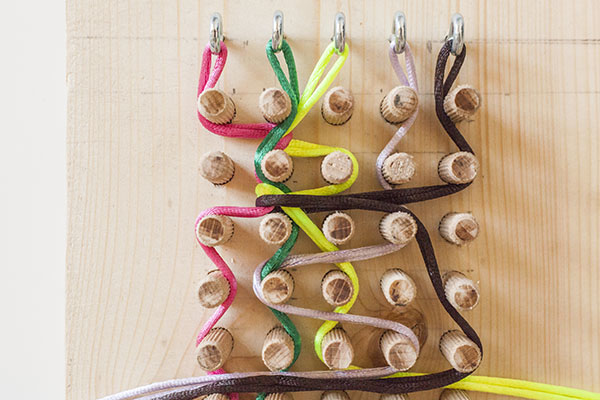
Producing knots
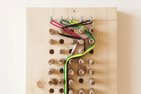
Coincidental synchronization-algorithm: all threads end up in the same place
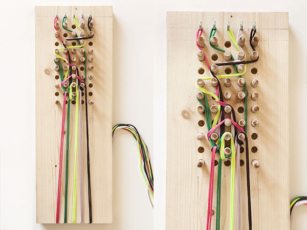
Complexity + knots by following the "clipboard" order and a simple algorithm: left, right, ...
Networks
How can we visualize or encode networks in a different way than we are used to ?
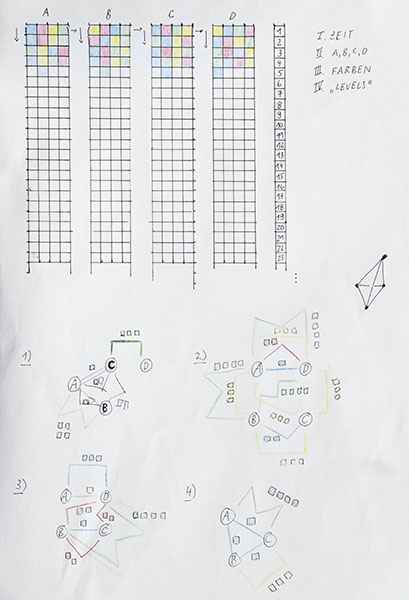
This sketch is a proposal to transform networks and their different parameters by shaping braids / thread patterns.
It is not predictable that random braid configurations evolve into proper braid structures that can exist without any outer support.
Therefore the "machine" above ("braiding") shall be used to set up a thread-path that does not fall apart easily.
The structure of the transformation is defined by several parameters that represent different properties of the network.
Example:
- the network could visualize trading routes between cities
- the colors could then represent different goods, for instance: yellow = red pedal boats
- A,B,C and D represent the nodes of the network. In this case they could represent the cities.
- the amount of goods can be represented by the location of a color inside the four squares of A,B,.. counted from left to right.
If the second square of A is yellow than this could mean that city A has 200 paddle boats.
- now, a match of the colors AND the locations of the colors inside of A,B,C or D means that those two or more cities (nodes) exchange goods (are connected).
In this example: A and B's second squares are yellow -> those two cities trade 200 paddle boats.
- if there is no match then there is no connection.
The "braids" and the network drawings can be infinitely translated into each other.
Levers and Cranes
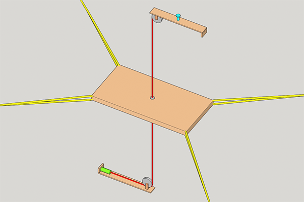
How can we move something in every three dimensional direction?
A mechanical feature of thread is that it can pull - but it can't push.
This structure helps to move things with thread by the use of additional mechanical support.
It is meant to be used by two peoples who operate two strings (yellow, each person) in order to move the object.
One important part of that structure is a spring (green).
It is attached to a fixed spot in the room. It stretches and contracts itself when the attached object is moved 1) parallel to the ground and 2) up and down.
Another essential aspect is the thread that goes through / is attached to the middle of the object.
It holds the object in place so that a precise movement is assured.
It also takes away some of the objects weight in order to exonerate the operator strings.
A third important part are the structures that attach the "middle-thread" (red) to the ceiling and the ground.
They 1) hold the middle-thread in place, they 2) react to the operators movements by turning in the required direction (blue wheel) and they 3) provide a bracket for the spring.
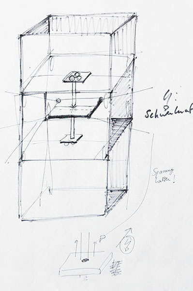
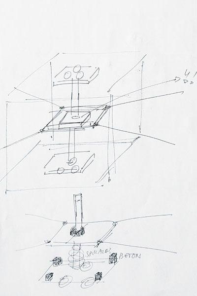
Sketches and previous versions:
Pulleys
This is an assembly kit that allows to work with pulley/thread constructions in a flexible way.
It works best with flat and smooth surfaces and it can be used in vertical and horizontal constructions
(such as logical operations, see Rachel Smith's and + or gates).
The parts:
1) 3D printed pulley wheels
2) metal ball bearings
3) plastic suction pads and
4) thread.
