GMU:Tutorials/Performance Platform/Videowall Calibration: Difference between revisions
From Medien Wiki
| Line 5: | Line 5: | ||
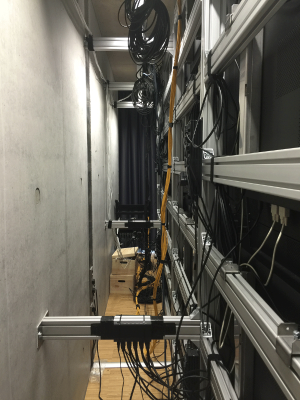
[[File:backofwall.png|thumb|left|Behind Video Wall|300px]] | [[File:backofwall.png|thumb|left|Behind Video Wall|300px]] | ||
[[File:screenbox.png|thumb|left|Signal Box|300px]] | [[File:screenbox.png|thumb|left|Signal Box|300px]] | ||
<br> | |||
Useful links: | Useful links: | ||
| Line 12: | Line 12: | ||
Manual: | Manual: | ||
[http://www.eyevis.de/files/um_eye-lcd-5500-xsn-ld-fx_en_v1.0_e03_1.pdf] | [http://www.eyevis.de/files/um_eye-lcd-5500-xsn-ld-fx_en_v1.0_e03_1.pdf] | ||
<br> | |||
<br style="clear:both"> | <br style="clear:both"> | ||
Revision as of 10:08, 28 July 2016
Introduction
The video wall consists of 4*4 screens, which are connected with each other with serial ports. And all the signal will processed by the signal box which will provide a HDMI port to connect to the computer. The signal from the computer can be then distributed through the box to each screen.
Useful links:
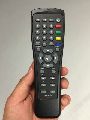
Part 1 With Remote Control
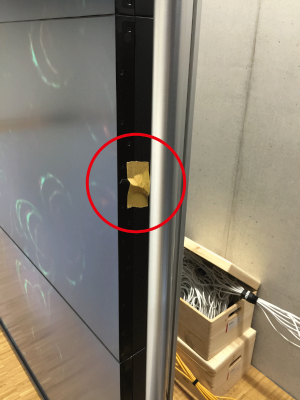
The infrared receiver is attached to the right side frame of the video wall. So the screen will react only when you target your remote control towards the infrared receiver.
When you press the menu button
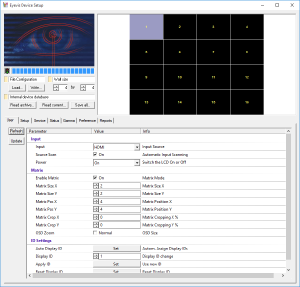
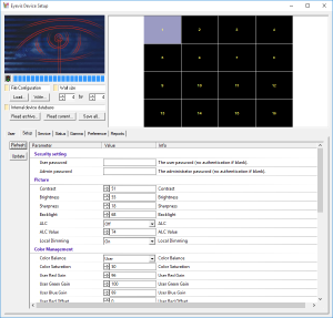
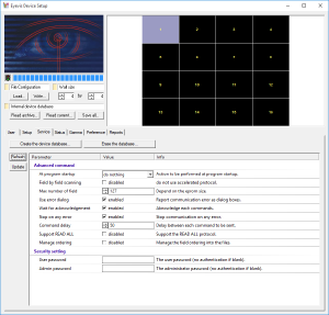
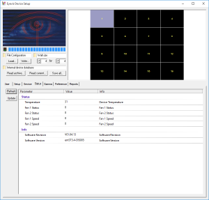
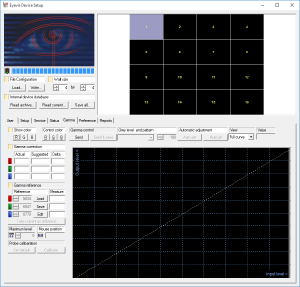
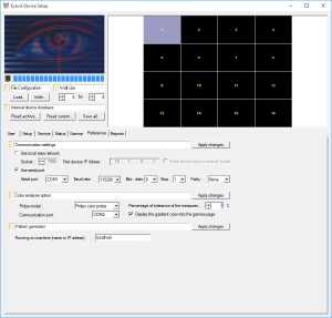
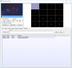
Part 2 With Software
Softwares will be used:
