No edit summary |
No edit summary |
||
| (26 intermediate revisions by the same user not shown) | |||
| Line 1: | Line 1: | ||
'''Analog Circuits and Interfaces'''<br /> | '''Analog Circuits and Interfaces'''<br /> | ||
''Instructor:'' [[Clemens Wegener]]<br/> | ''Instructor:'' [[Clemens Wegener]]<br/> | ||
''Credits:'' 6 [[ECTS]], 3 [[SWS]]<br/> | ''Credits:'' 6 [[ECTS]], 3 [[SWS]]<br/> | ||
Project by Paul and Joel Schaefer | Project by Paul Plattner and Joel Schaefer | ||
{| border="1" | {| border="1" | ||
| Line 10: | Line 9: | ||
|- | |- | ||
[[File:Front2.PNG|Prototype|600px]] | |||
[[File:Front1.png |Prototype|600px]] | |||
[[File:CVInterface1.jpeg|Prototype|600px]] | [[File:CVInterface1.jpeg|Prototype|600px]] | ||
[[File:CVInterface3.jpg |Prototype|600px]] | [[File:CVInterface3.jpg |Prototype|600px]] | ||
|- | |- | ||
|} | |} | ||
<br/> | |||
<br/> | |||
The inspiration for making this device was the old "A-174-1 Joy Stick" Module by Doepfer and the famous Eurorack Interface ES-X series by Expert Sleepers. The reason for our interest in a Joystick as Control element for analog devices is simply the functional advantage its having, meaning the possibilty to tweak 2 Values with 1 Movement. The interest in dc coupled Interfaces like the Expert Sleepers series is obvious. The idea of generating and receiving control voltage in a digital environment on the pc with software like "CV Tools" by Ableton seems to be pretty interesting. Not just for the sake of an easier and accurate way to generate Control Voltage, no also in the sense of communication between devices and softwares. For example, to make generative Computergraphics with Software like Unity, TouchDesigner or Blender and use control voltage from your Modular Synth to control aspects of the generative Video Output. Or the other way around to generate Video Output inside such software through different functions and to use this data also for the generation of sound through Analog Synthesizers. Not to mention feedback loops. So, we think a dc coupled interface that bridges the world of analog and digital without the use of the extremely quality dropping MIDI protocol is a thing that holds a very big potential for many artistically interesting uses. | The inspiration for making this device was the old "A-174-1 Joy Stick" Module by Doepfer and the famous Eurorack Interface ES-X series by Expert Sleepers. The reason for our interest in a Joystick as Control element for analog devices is simply the functional advantage its having, meaning the possibilty to tweak 2 Values with 1 Movement. The interest in dc coupled Interfaces like the Expert Sleepers series is obvious. The idea of generating and receiving control voltage in a digital environment on the pc with software like "CV Tools" by Ableton seems to be pretty interesting. Not just for the sake of an easier and accurate way to generate Control Voltage, no also in the sense of communication between devices and softwares. For example, to make generative Computergraphics with Software like Unity, TouchDesigner or Blender and use control voltage from your Modular Synth to control aspects of the generative Video Output. Or the other way around to generate Video Output inside such software through different functions and to use this data also for the generation of sound through Analog Synthesizers. Not to mention feedback loops. So, we think a dc coupled interface that bridges the world of analog and digital without the use of the extremely quality dropping MIDI protocol is a thing that holds a very big potential for many artistically interesting uses. | ||
Anyway, as dc coupled interfaces appear to be not very common and quite expensive on the market of audio interfaces we wanted to create a similiar device ourself thats able to send and receive analog Signals over USB connection. | Anyway, as dc coupled interfaces appear to be not very common and quite expensive on the market of audio interfaces we wanted to create a similiar device ourself thats able to send and receive analog Signals over USB connection. | ||
| Line 36: | Line 38: | ||
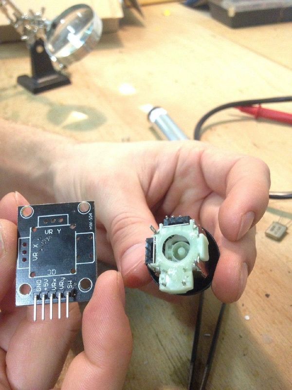
So now, when we got the cv in- and outputs working it was time to get joystick and potentiometers. We just buyed a cheap Joystick and some 10k Potentiometers. In the first place we were disappointed by the Joystick. The accuracy was extremely low and the spring inside the joystick made it even worse for the usage of accurate voltage generation. So we decided to use 2 channels of the external 16 Bit ADC for the YX-Axis inputs for making the joystick more accurate. And we desoldered the Joystick Circuit, drilled a whole inside and took out the spring. Luckily we orded a 5-Pack of Joysticks instead of just one, because 2 Joysticks got broken in this procedure. The third one was working perfect. | So now, when we got the cv in- and outputs working it was time to get joystick and potentiometers. We just buyed a cheap Joystick and some 10k Potentiometers. In the first place we were disappointed by the Joystick. The accuracy was extremely low and the spring inside the joystick made it even worse for the usage of accurate voltage generation. So we decided to use 2 channels of the external 16 Bit ADC for the YX-Axis inputs for making the joystick more accurate. And we desoldered the Joystick Circuit, drilled a whole inside and took out the spring. Luckily we orded a 5-Pack of Joysticks instead of just one, because 2 Joysticks got broken in this procedure. The third one was working perfect. | ||
<br/> | |||
[[File:Joystickhack.jpeg|600px]] <br/> | |||
<br/> | |||
Then we decided to use the whole potential the arduino is giving us with its 6 internal ADC's and connected 4 Knob Potentiometers and 2 Slider Potentiometers to it. These should control different values of our functions on the arduino. | Then we decided to use the whole potential the arduino is giving us with its 6 internal ADC's and connected 4 Knob Potentiometers and 2 Slider Potentiometers to it. These should control different values of our functions on the arduino. | ||
Though we didn't had much functions written yet, we knew we would make different modes. So we got some LED's (1 blue, 3 red) for indicating different modes and also we took a switch button breakout board for changing modes. Another switch button we had available through the joystick itself, because this one had a push function. | Though we didn't had much functions written yet, we knew we would make different modes. So we got some LED's (1 blue, 3 red) for indicating different modes and also we took a switch button breakout board for changing modes. Another switch button we had available through the joystick itself, because this one had a push function. | ||
| Line 41: | Line 46: | ||
Hardware fully set up, now it's time for the digtal stuff. | Hardware fully set up, now it's time for the digtal stuff. | ||
Our basic idea responds into the simple function to express the XY-Axis of the Joystick as 2 Values that are linearly mapped onto Out CV1 and Out CV2. So one axis gave us values between 0 and ~25000, which we simply mapped onto 0-10V. The following was to make a function which is summing the two axis into one value. We simply wrote a average function which, when activated, sums the the two Joystick values and maps them once again to 0-10V. We called this "Sum-Mode" and its accesible through pushing the joystick button one time. The State of these two Modes is indicated through the blue LED (on - SumMode [Out CV 1 = Out CV 2] , off - NormalMode [Out CV 1 = X-Axis ; Out CV2 = Y-Axis]). So the second CV Output becomes a copy of the first when the SumMode is active. So this Mode could also be used as a multiple. | Our basic idea responds into the simple function to express the XY-Axis of the Joystick as 2 Values that are linearly mapped onto Out CV1 and Out CV2. So one axis gave us values between 0 and ~25000, which we simply mapped onto 0-10V. The following was to make a function which is summing the two axis into one value. We simply wrote a average function which, when activated, sums the the two Joystick values and maps them once again to 0-10V. We called this "Sum-Mode" and its accesible through pushing the joystick button one time. The State of these two Modes is indicated through the blue LED (on - SumMode [Out CV 1 = Out CV 2] , off - NormalMode [Out CV 1 = X-Axis ; Out CV2 = Y-Axis]). So the second CV Output becomes a copy of the first when the SumMode is active. So this Mode could also be used as a multiple. | ||
To not get users confused its important to say that these are global modi, which | To not get users confused its important to say that these are global modi, which both work in the same way, no matter which of the following (local) modes is chosen. | ||
These are the Local Modes so far: | These are the Local Modes so far: <br/> | ||
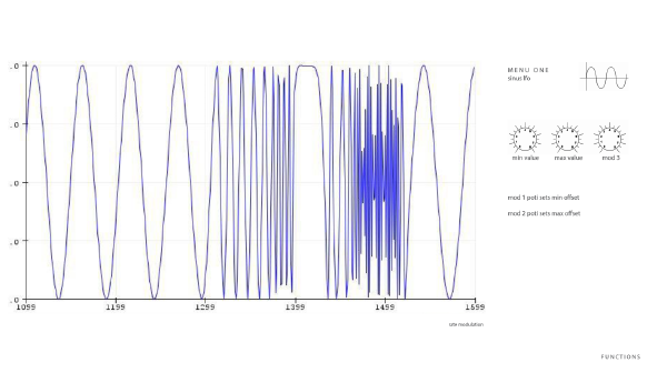
1. Sine LFO | 1. Sine LFO <br/> | ||
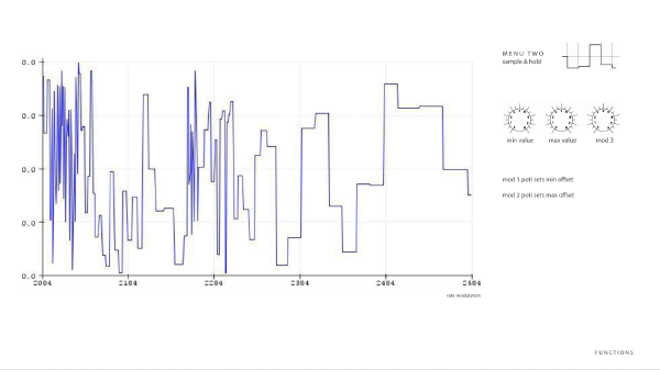
2. Sample and Hold internal | 2. Sample and Hold internal <br/> | ||
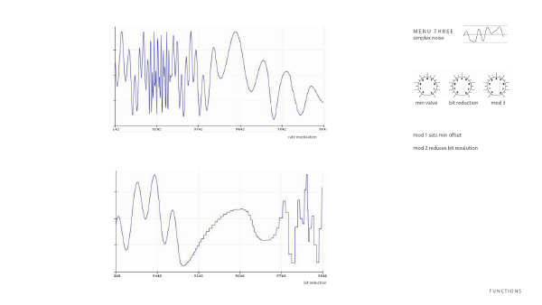
3. Simplex Noise | 3. Simplex Noise <br/> | ||
4. Sample and Hold external | 4. Sample and Hold external <br/> | ||
<br/> | |||
<br/> | |||
1<br/> | |||
[[File:Mode1.PNG|LFOSINE|600px]] | |||
<br/> | |||
2<br/> | |||
[[File:Mode2.PNG|intSH|600px]] | |||
<br/> | |||
3<br/> | |||
[[File:Mode3.PNG|Simplex|600px]] | |||
<br/> | |||
4<br/> | |||
[[File:Mode4.png|extSH|600px]] | |||
<br/> | |||
The idea of these modes is to mix the voltage generated by the Joystick with different functions. Or, in other words, to make the joystick controlling an offset to different functions. | The idea of these modes is to mix the voltage generated by the Joystick with different functions. Or, in other words, to make the joystick controlling an offset to different functions. Of course, if the Joystick is placed in the left-down corner the offset value is 0 on both axis'. That means if the amount value in any Mode is completely up, the output voltage is completely generated by the function. | ||
Conclusion | |||
Conclusion <br/> | |||
This circuit is really a raw prototype, so there are many things to mention. | This circuit is really a raw prototype, so there are many things to mention. | ||
On the hardware side we want to add an analog offset for the output Voltages. We think that would make sense because then we would be able to fade between the range between 0V to 10V and -5V to 5V, which definetely is useful for the use in modular systems. But as the interface got already pretty packed up with potentiometers and (digital) offset functionalities, we we will implement this feature with a simple switch to change the output range between bipolar and unipolar. | |||
Its extremely important to add a voltage limiting circuit with diodes to both CV/Clock Inputs because right now a voltage over 11V or below -1V could damage the ADC board. Though signals over 10V are pretty uncommon in modular synthesizers and eurorack, bipolar signals from -5V to 5V or even -10V to 10V are not. | Its extremely important to add a voltage limiting circuit with diodes to both CV/Clock Inputs because right now a voltage over 11V or below -1V could damage the ADC board. Though signals over 10V are pretty uncommon in modular synthesizers and eurorack, bipolar signals from -5V to 5V or even -10V to 10V are not. | ||
So for the harmless and free use of the CV input there need to be such circuit. As well as an additional OpAmp Buffer for those inputs. | So for the harmless and free use of the CV input there need to be such circuit. As well as an additional OpAmp Buffer for those inputs. | ||
Then there need to be functionality added to the CV Input, because right now its only possible to use 1 Input as Gate Input for clocking the Sample Hold external Mode. But there are many uses for such Input. One could just be voltage conversion, so when the device is connected over usb, the, now digital data could be send via serial connection to other software as "Processing". Another way would be to implement OSC protocol to the code and make this incoming Voltage available as OSC data for the reuse by other software applications. | Then there need to be functionality added to the CV Input, because right now its only possible to use 1 Input as Gate Input for clocking the Sample Hold external Mode. But there are many uses for such Input. One could just be voltage conversion, so when the device is connected over usb, the, now digital data could be send via serial connection to other software as "Processing". Another way would be to implement OSC protocol to the code and make this incoming Voltage available as OSC data for the reuse by other software applications. | ||
Another way to use the CV input would be the modulation of internal parameters. For example the rate of the Sine LFO in that Mode(1) or the bitReduction Amount Parameter of the Simplex Noise Mode(3). | Another way to use the CV input would be the modulation of internal parameters. For example the rate of the Sine LFO in that Mode(1) or the bitReduction Amount Parameter of the Simplex Noise Mode(3). | ||
| Line 67: | Line 89: | ||
After that said, we want to name and explain some functionalities we want to add in the future. | After that said, we want to name and explain some functionalities we want to add in the future. | ||
Extend existing functions: | <br/> | ||
<br/> | |||
Extend existing functions:<br/> | |||
*General | |||
-higher Range of available Speed for Audio Range Modulation Purposes <br/> | |||
-Modulation of Parameters through CV in <br/> | |||
-simultaneous Modes <br/> | |||
*Sine LFO | |||
-more Shapes by using Wavetables | |||
*Sample & Hold | |||
-Interpolation Amount for fading into Smoothed Random | |||
<br/> | |||
<br/> | |||
Add new functions: | |||
<br/> | |||
* "Quantizator" <br/> | |||
The, not yet existing "special knob" in the upper right corner of the circuit was intended for that. This function should not be another Mode which has to be selected like the other Modes. It should more be something like a filter at the end of the processing chain. When turned down, the output voltage isn't not affected. When turning up, the output voltage got slowy quantized into semitones. When it's halfway turned, the Output should spit out 12 Values per 1 Voltage, so 120 values or "notes" in the full range. That means it can play analog synthesizers musically over 10 octaves. When this "special knob" got turned above the half, it slowy fades the 12 semitones per 1 Volt into less and specific ones. By this, the device is able to turn any signal, no matter if generated, processed or just incoming into a musical scale. Which scale exactly shall be also choosable by the user over an extra button which switches between different scales. | The, not yet existing "special knob" in the upper right corner of the circuit was intended for that. This function should not be another Mode which has to be selected like the other Modes. It should more be something like a filter at the end of the processing chain. When turned down, the output voltage isn't not affected. When turning up, the output voltage got slowy quantized into semitones. When it's halfway turned, the Output should spit out 12 Values per 1 Voltage, so 120 values or "notes" in the full range. That means it can play analog synthesizers musically over 10 octaves. When this "special knob" got turned above the half, it slowy fades the 12 semitones per 1 Volt into less and specific ones. By this, the device is able to turn any signal, no matter if generated, processed or just incoming into a musical scale. Which scale exactly shall be also choosable by the user over an extra button which switches between different scales. | ||
<br/> | |||
*Envelopes <br/> | |||
Just a classic clockable AD-Envelope generator. Also loopable, when no Gate Signal is received. As expected, Decay time shall be modulatable by CV input. | |||
<br/> | |||
<br/> | |||
<br/> | |||
Further things: | |||
<br/> | |||
*USB Audio CODEC<br/> | |||
To use this device directly without OSC or Serial data transfers with other Software like "CV Tools", like the Expert Sleeper Devices we mentioned in the beginning, it must be recognized as an audio interface. | |||
<br/> | |||
*Panel Design<br/> | |||
*Eurorack Format and Power Supply<br/> | |||
Latest revision as of 01:50, 2 March 2020
Analog Circuits and Interfaces
Instructor: Clemens Wegener
Credits: 6 ECTS, 3 SWS
Project by Paul Plattner and Joel Schaefer
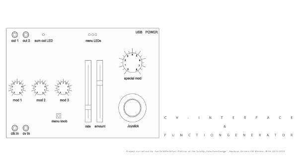
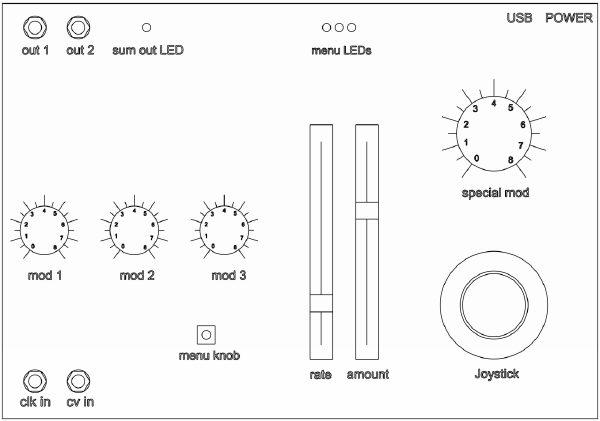
The inspiration for making this device was the old "A-174-1 Joy Stick" Module by Doepfer and the famous Eurorack Interface ES-X series by Expert Sleepers. The reason for our interest in a Joystick as Control element for analog devices is simply the functional advantage its having, meaning the possibilty to tweak 2 Values with 1 Movement. The interest in dc coupled Interfaces like the Expert Sleepers series is obvious. The idea of generating and receiving control voltage in a digital environment on the pc with software like "CV Tools" by Ableton seems to be pretty interesting. Not just for the sake of an easier and accurate way to generate Control Voltage, no also in the sense of communication between devices and softwares. For example, to make generative Computergraphics with Software like Unity, TouchDesigner or Blender and use control voltage from your Modular Synth to control aspects of the generative Video Output. Or the other way around to generate Video Output inside such software through different functions and to use this data also for the generation of sound through Analog Synthesizers. Not to mention feedback loops. So, we think a dc coupled interface that bridges the world of analog and digital without the use of the extremely quality dropping MIDI protocol is a thing that holds a very big potential for many artistically interesting uses. Anyway, as dc coupled interfaces appear to be not very common and quite expensive on the market of audio interfaces we wanted to create a similiar device ourself thats able to send and receive analog Signals over USB connection.
So we we decided to use an Arduino Uno for our project. The starting point was this great, creative common released, open hardware device we found on github.
https://github.com/eegsynth/eegsynth/tree/master/hardware/usb2cvgate_4channel
Its designed by Robert Oostenveld for eegsynth.org. This is the original Schematic:
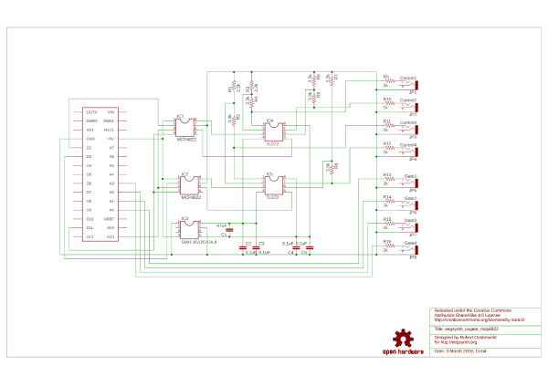
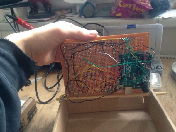
It converts digital data from the arduino (connected through SDI) over an external 12Bit DAC to 0-4V and scales the range over an OpAmp to 0-10V. This device is able to do this on 4 channels, for us 2 was enough, so we cutted away the half of the original circuit. Also we skipped the 4 Gate Outputs. So what we were having then was basically one 12Bit DAC (MCP4822), one OpAmp (TL072) and one DC-DC Converter (SIM 0512D) and the needed resitors and capacitors which can be seen in the original schematic. The only thing that was missing for us in terms of Data Conversion was CV-Inputs. So an ADC was needed. As the resolution of the arduino 10Bit ADC's was to low for us, we buyed a 16Bit 4ch ADC. The ADS1115 Breakout Board by Adafruit. We connected this device also over SDI to the arduino. We installed 2 more Audio-Jacks for the input signals, set a little voltage divider with 100k resistors behind that Jack to scale the incoming Voltage to an acceptable Level for the ADC(max 5.5V). For sure this isn't the best way to do it, especially without an extra OpAmp as buffer and diode based protection circuit, but for this prototype it worked fine for us.
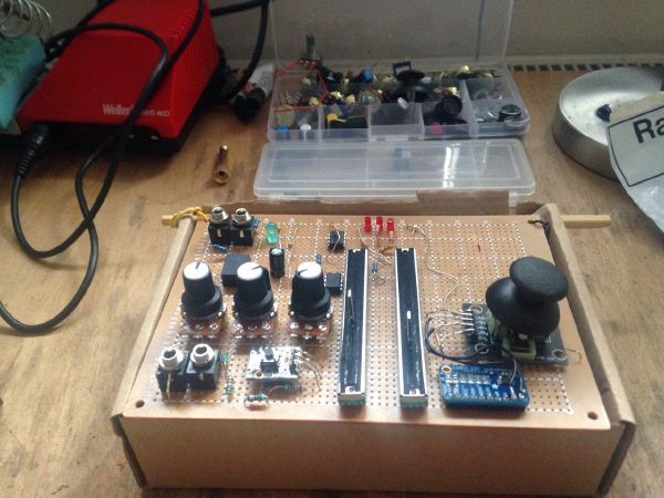
So now, when we got the cv in- and outputs working it was time to get joystick and potentiometers. We just buyed a cheap Joystick and some 10k Potentiometers. In the first place we were disappointed by the Joystick. The accuracy was extremely low and the spring inside the joystick made it even worse for the usage of accurate voltage generation. So we decided to use 2 channels of the external 16 Bit ADC for the YX-Axis inputs for making the joystick more accurate. And we desoldered the Joystick Circuit, drilled a whole inside and took out the spring. Luckily we orded a 5-Pack of Joysticks instead of just one, because 2 Joysticks got broken in this procedure. The third one was working perfect.
Then we decided to use the whole potential the arduino is giving us with its 6 internal ADC's and connected 4 Knob Potentiometers and 2 Slider Potentiometers to it. These should control different values of our functions on the arduino. Though we didn't had much functions written yet, we knew we would make different modes. So we got some LED's (1 blue, 3 red) for indicating different modes and also we took a switch button breakout board for changing modes. Another switch button we had available through the joystick itself, because this one had a push function.
Hardware fully set up, now it's time for the digtal stuff. Our basic idea responds into the simple function to express the XY-Axis of the Joystick as 2 Values that are linearly mapped onto Out CV1 and Out CV2. So one axis gave us values between 0 and ~25000, which we simply mapped onto 0-10V. The following was to make a function which is summing the two axis into one value. We simply wrote a average function which, when activated, sums the the two Joystick values and maps them once again to 0-10V. We called this "Sum-Mode" and its accesible through pushing the joystick button one time. The State of these two Modes is indicated through the blue LED (on - SumMode [Out CV 1 = Out CV 2] , off - NormalMode [Out CV 1 = X-Axis ; Out CV2 = Y-Axis]). So the second CV Output becomes a copy of the first when the SumMode is active. So this Mode could also be used as a multiple. To not get users confused its important to say that these are global modi, which both work in the same way, no matter which of the following (local) modes is chosen.
These are the Local Modes so far:
1. Sine LFO
2. Sample and Hold internal
3. Simplex Noise
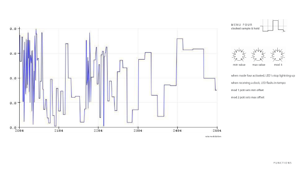
4. Sample and Hold external
1
2
3
4
The idea of these modes is to mix the voltage generated by the Joystick with different functions. Or, in other words, to make the joystick controlling an offset to different functions. Of course, if the Joystick is placed in the left-down corner the offset value is 0 on both axis'. That means if the amount value in any Mode is completely up, the output voltage is completely generated by the function.
Conclusion
This circuit is really a raw prototype, so there are many things to mention.
On the hardware side we want to add an analog offset for the output Voltages. We think that would make sense because then we would be able to fade between the range between 0V to 10V and -5V to 5V, which definetely is useful for the use in modular systems. But as the interface got already pretty packed up with potentiometers and (digital) offset functionalities, we we will implement this feature with a simple switch to change the output range between bipolar and unipolar.
Its extremely important to add a voltage limiting circuit with diodes to both CV/Clock Inputs because right now a voltage over 11V or below -1V could damage the ADC board. Though signals over 10V are pretty uncommon in modular synthesizers and eurorack, bipolar signals from -5V to 5V or even -10V to 10V are not. So for the harmless and free use of the CV input there need to be such circuit. As well as an additional OpAmp Buffer for those inputs.
Then there need to be functionality added to the CV Input, because right now its only possible to use 1 Input as Gate Input for clocking the Sample Hold external Mode. But there are many uses for such Input. One could just be voltage conversion, so when the device is connected over usb, the, now digital data could be send via serial connection to other software as "Processing". Another way would be to implement OSC protocol to the code and make this incoming Voltage available as OSC data for the reuse by other software applications. Another way to use the CV input would be the modulation of internal parameters. For example the rate of the Sine LFO in that Mode(1) or the bitReduction Amount Parameter of the Simplex Noise Mode(3). Or, simply to add an offset by the joystick to an incoming signal.
At this point it's right to mention that the parts we choose for our circuit are not really fitting each other. Because when we receive a incoming signal at 16Bits, process it in any way, and then send it out at 12Bits, there is an enourmous amount of quality loss because of the resolution drop. So, perspectively it makes much more sense to use the same Resolution for the DAC's and ADC's. Or at least an higher Resolution on the DAC then on the ADC. So in the future we will exchange the current 12Bit DAC by an 16Bit DAC.
Then, shortly before the final presentation we realized that two of our potentiometers weren't working. On the picture at the top of this page can only 1 still be seen, the free space in the right corner of the circuit was actually holded for the 4. Potentiometer. But as we figured out that the problem was laying inside two of the analog Inputs of the arduino itself, we decided to remove the 4. one for now. As we were having an indifference between the digital functionality and the possibilities our hardware setup gave us at this point, it wasn't a problem. The lack of more sophisticated functions was more connected to the fact that it took us too much time to write the functions. The lack of knowledge in writing code for such purposes was actually the biggest problem that occured in the realization of this project. Because our both amateurish coding knowledge doesn't include bitwise operators at all. And so doesn't our coding approach in this project. That means we used a ton of global variables to provide our functions working. This results in 80% cpu usage with really not that many or complex features yet. That is not practicible for the future at all. So the optimization of the code is really the most important thing for further developing this circuit.
After that said, we want to name and explain some functionalities we want to add in the future.
Extend existing functions:
- General
-higher Range of available Speed for Audio Range Modulation Purposes
-Modulation of Parameters through CV in
-simultaneous Modes
- Sine LFO
-more Shapes by using Wavetables
- Sample & Hold
-Interpolation Amount for fading into Smoothed Random
Add new functions:
- "Quantizator"
The, not yet existing "special knob" in the upper right corner of the circuit was intended for that. This function should not be another Mode which has to be selected like the other Modes. It should more be something like a filter at the end of the processing chain. When turned down, the output voltage isn't not affected. When turning up, the output voltage got slowy quantized into semitones. When it's halfway turned, the Output should spit out 12 Values per 1 Voltage, so 120 values or "notes" in the full range. That means it can play analog synthesizers musically over 10 octaves. When this "special knob" got turned above the half, it slowy fades the 12 semitones per 1 Volt into less and specific ones. By this, the device is able to turn any signal, no matter if generated, processed or just incoming into a musical scale. Which scale exactly shall be also choosable by the user over an extra button which switches between different scales.
- Envelopes
Just a classic clockable AD-Envelope generator. Also loopable, when no Gate Signal is received. As expected, Decay time shall be modulatable by CV input.
Further things:
- USB Audio CODEC
To use this device directly without OSC or Serial data transfers with other Software like "CV Tools", like the Expert Sleeper Devices we mentioned in the beginning, it must be recognized as an audio interface.
- Panel Design
- Eurorack Format and Power Supply
