No edit summary |
No edit summary |
||
| (One intermediate revision by the same user not shown) | |||
| Line 1: | Line 1: | ||
Inspiration: | Inspiration: | ||
[[:File:Inspiration Präsentation Erkan.pdf]] | [[:File:Inspiration Präsentation Erkan.pdf]] | ||
Documentation: | |||
PDF of the Documentation: | |||
[[:File:PCBartsdoku.pdf]] | [[:File:PCBartsdoku.pdf]] | ||
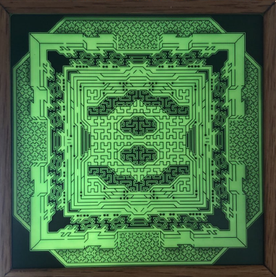
I planned to create an unfunctional PCB-design using the tools and aesthetics of a classic PCB. I decided to only use angles of 90 and 45 degrees to create patterns. I started working in ''KICAD'' and using ''PCBnew'' to create different patterns. Being able to rotate and mirror the copper tracks was a huge help to get big and consistent patterns faster. After looking at some PCBs that i found at home and holding them in front of a computer screen, I saw that light can shine through the PCBs if there is no copper in the area where the light is trying to pass. This creates shadows the viewer can see from the other side. So I decided to use this feature of the PCBs for my artistic approach and tried to apply shadows to give some threedimensional character to the picture I was creating. | |||
[[File:pcbdokupic1.png|400px]] | |||
'' A picture of the PCB with sunlight going through. '' | |||
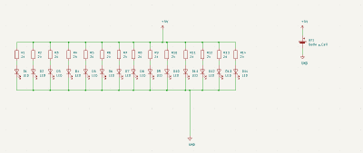
To increase this effect I edited the mask layer on the backsite of the PCB so, that there is only mask left where I wanted to place shadows on the front. Like this the light can shine through better. Knowing that these shadows would only appear if there is light shining through the backside of the PCB, I wanted to create another PCB with LEDs on it to make a backlight. Of course this PCB would have the same size as the other because I wanted to put it inside a frame, so the backlighting PCB would not be seen. I created another PCB and used ''ledcalculator.net'' for the scheme I had to use with the number of LEDs i wanted to use. | |||
[[File:pcbdokupic2.png|400px]] | |||
I put the LEDs in even distances next to another so the light would shine through equally on all the areas of the frontplate. When it came to ordering the PCBs I found out it was not as cheap as I thought. I ended up only ordering the frontplate as I had some LEDs at home and wanted to build the backlight myself. The next step was to build a frame for the picture. I had problems to adjust the size of the single elements of the frame as I did not have the right tools to measure distance precisely and cut the wood in 45° angles at the same time. Using a little more woodglue to fill the resulting gaps between the angles holds the frame together pretty good. From this point on I experimented with some LEDs and found out that the frame was too small in depth to create an even backlighting inside the frame. The LEDs would always be too close to the frontplate and created areas with too much light in comparison to the other areas. Using some kind of paper between the LEDs and the frontplate would have helped a lot with that problem, but i sadly did not have enough space inside the frame. Therefore I decided not to use LEDs for backlighting the first prototype, as I also found out sunlight is much more beautifull when it shines through the frontplate and also gives a different view on the picture depending on the position of the sun. Yet I still want to create another version with consistent LED backlighting, but for that I need to build a bigger frame. I will update the wiki when I have done so. The ''KICAD'' projects can be found on ''Github''. https://github.com/erk4ns/kicadpcbarts | |||
[[File:pcbdokupic3.png|400px]][[File:pcbdokupic4.png|400px]] | |||
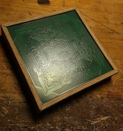
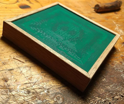
''Some pictures of the PCB right after building the frame.'' | |||
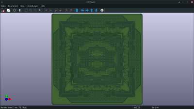
[[File:pcbdokupic5.png|400px]] | |||
''The 3D view of the frontdesign.'' | |||
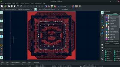
[[File:pcbdokupic6.png|400px]] | |||
''The copper on the front of the PCB.'' | |||
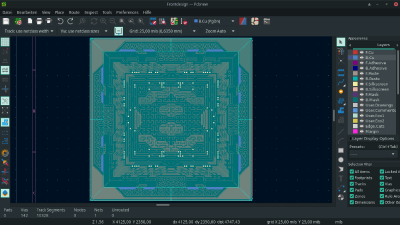
[[File:pcbdokupic7.png|400px]] | |||
''The maskfree area on the backside is completly filling out the PCB except for the areas where I also put the copper on the backside.'' | |||
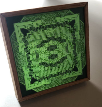
[[File:pcbdokupic8.png|400px]] | |||
''The PCB inside the frame and some natural light.'' | |||
Latest revision as of 10:31, 2 April 2021
Inspiration: File:Inspiration Präsentation Erkan.pdf
PDF of the Documentation: File:PCBartsdoku.pdf
I planned to create an unfunctional PCB-design using the tools and aesthetics of a classic PCB. I decided to only use angles of 90 and 45 degrees to create patterns. I started working in KICAD and using PCBnew to create different patterns. Being able to rotate and mirror the copper tracks was a huge help to get big and consistent patterns faster. After looking at some PCBs that i found at home and holding them in front of a computer screen, I saw that light can shine through the PCBs if there is no copper in the area where the light is trying to pass. This creates shadows the viewer can see from the other side. So I decided to use this feature of the PCBs for my artistic approach and tried to apply shadows to give some threedimensional character to the picture I was creating.
A picture of the PCB with sunlight going through.
To increase this effect I edited the mask layer on the backsite of the PCB so, that there is only mask left where I wanted to place shadows on the front. Like this the light can shine through better. Knowing that these shadows would only appear if there is light shining through the backside of the PCB, I wanted to create another PCB with LEDs on it to make a backlight. Of course this PCB would have the same size as the other because I wanted to put it inside a frame, so the backlighting PCB would not be seen. I created another PCB and used ledcalculator.net for the scheme I had to use with the number of LEDs i wanted to use.
I put the LEDs in even distances next to another so the light would shine through equally on all the areas of the frontplate. When it came to ordering the PCBs I found out it was not as cheap as I thought. I ended up only ordering the frontplate as I had some LEDs at home and wanted to build the backlight myself. The next step was to build a frame for the picture. I had problems to adjust the size of the single elements of the frame as I did not have the right tools to measure distance precisely and cut the wood in 45° angles at the same time. Using a little more woodglue to fill the resulting gaps between the angles holds the frame together pretty good. From this point on I experimented with some LEDs and found out that the frame was too small in depth to create an even backlighting inside the frame. The LEDs would always be too close to the frontplate and created areas with too much light in comparison to the other areas. Using some kind of paper between the LEDs and the frontplate would have helped a lot with that problem, but i sadly did not have enough space inside the frame. Therefore I decided not to use LEDs for backlighting the first prototype, as I also found out sunlight is much more beautifull when it shines through the frontplate and also gives a different view on the picture depending on the position of the sun. Yet I still want to create another version with consistent LED backlighting, but for that I need to build a bigger frame. I will update the wiki when I have done so. The KICAD projects can be found on Github. https://github.com/erk4ns/kicadpcbarts
Some pictures of the PCB right after building the frame.
The 3D view of the frontdesign.
The copper on the front of the PCB.
The maskfree area on the backside is completly filling out the PCB except for the areas where I also put the copper on the backside.
The PCB inside the frame and some natural light.
