No edit summary |
|||
| (11 intermediate revisions by the same user not shown) | |||
| Line 1: | Line 1: | ||
[[File:WindThing.jpg|70vw]] | [[File:WindThing.jpg|70vw]] | ||
==Concept== | |||
===What is it?=== | |||
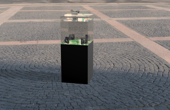
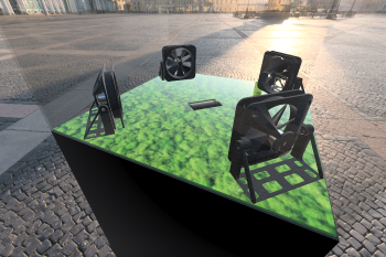
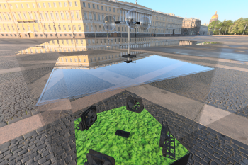
In this installation wind is captured outdoors, then transmitted and reproduced in a hermetic like glass cube right underneath. Receipt paper is slowly intruded into the space and blown by four fans, in the direction and the speed from the wind outside. To cover the whole room the fans are positioned in the corners, instead the corners would be left out and paper would get stuck. The uselessness of the reproduction of wind in the same direction, the same speed and at the exact same spot, just in an enclosed and isolated space . Like in a museum or a zoo the wind can be observed, but what can we learn from it? Is the wind an old relict that is worth to be presented in a museum? Or is the wind, like a fish in a fishtank, something that needs to be kept alive? | |||
Furthermore, this installation will be split into two parts, so it can be presented in two different contexts. The first one is for public art, the wind is, as described above reproduced live and at the exact same spot. Then, the second part would be presented in a gallery or other indoor exhibition spaces like a museum. For this case the data from part one is written on an SD card and then in the gallery recalled and played on the fans. This would be the exact echo or memory of the wind that was once there, but isn't anymore. | |||
[[File:FinalBuilt.jpg|350px]] | |||
{{#ev:vimeo|674244737}} | {{#ev:vimeo|674244737}} | ||
==Technical== | ===Technical=== | ||
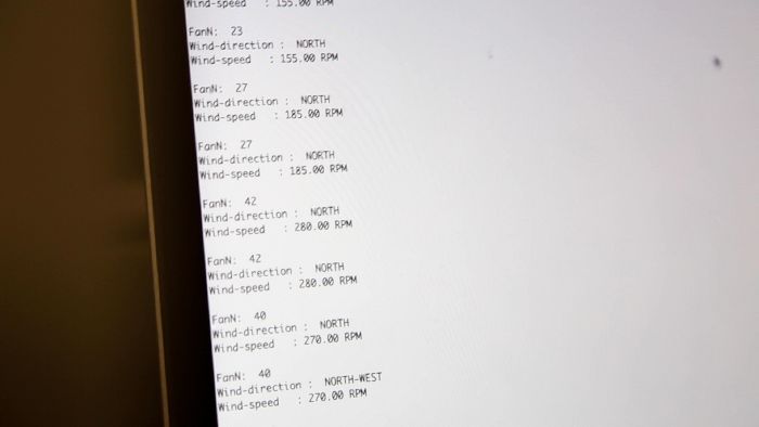
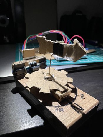
To capture the wind speed and and the direction, a DIY anemometer is built. For both, photo interrupters are used. To measure the wind speed, a slotted disk is used to measure the amount of steps (on/off) in a certain time and then calculated to rpm, which will be send to control the speed of the fans. For capturing the direction, a rotary encoder is built with two photo interrupters and also a disk, that has eight on and eight off steps (for eight wind directions). | To capture the wind speed and and the direction, a DIY anemometer is built. For both, photo interrupters are used. To measure the wind speed, a slotted disk is used to measure the amount of steps (on/off) in a certain time and then calculated to rpm, which will be send to control the speed of the fans. For capturing the direction, a rotary encoder is built with two photo interrupters and also a disk, that has eight on and eight off steps (for eight wind directions). | ||
The use of an Arduino Mega is necessary to provide enough digital inputs that support interrupts, but also enough outputs for the motor controllers. For the fans, brushless motors are used, that are also very common in drones, e-bikes, etc. They are controlled with ESC motor drivers and powered by RC batteries, so the installation can stand independently from a power socket. | The use of an Arduino Mega is necessary to provide enough digital inputs that support interrupts, but also enough outputs for the motor controllers. For the fans, brushless motors are used, that are also very common in drones, e-bikes, etc. They are controlled with ESC motor drivers and powered by RC batteries, so the installation can stand independently from a power socket. | ||
File:ArduinoWiring.jpg | [[File:ArduinoWiring.jpg|350px]] | ||
File:MotorWindThing.jpg | [[File:MotorWindThing.jpg|350px]] | ||
==Aesthetics== | ===Aesthetics=== | ||
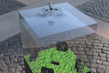
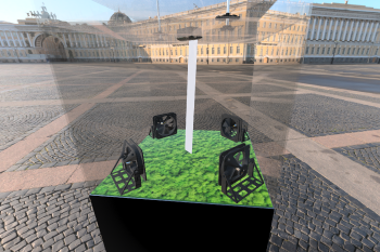
It is all happening in a hermetic like glass cube that is sitting on a plinth. The parts are 3D printed to look neat and integrate into the installation, but still the DIY aesthetics should come out. In the cube a layer of moss is placed which on one hand is representing nature, but is also a great natural air filter. In the center on the top of the inside there is an extruder to feed the box with paper, the paper is used as an indicator for the wind and at the same time it's interesting to see what happens when the box gets slowly filled with the paper. The DIY sensors can be seen inside a transparent box that is sitting on top of the cube, so people can see what exactly is happening and can relate to the things happening inside the box. | It is all happening in a hermetic like glass cube that is sitting on a plinth. The parts are 3D printed to look neat and integrate into the installation, but still the DIY aesthetics should come out. In the cube a layer of moss is placed which on one hand is representing nature, but is also a great natural air filter. In the center on the top of the inside there is an extruder to feed the box with paper, the paper is used as an indicator for the wind and at the same time it's interesting to see what happens when the box gets slowly filled with the paper. The DIY sensors can be seen inside a transparent box that is sitting on top of the cube, so people can see what exactly is happening and can relate to the things happening inside the box. | ||
[[File:Render1.png| | [[File:Render1.png|700px]][[File:Render2.png|350px]][[File:Render_new.png|350px]] | ||
[[File:Render4.png|350px]][[File:Render5.png|350px]] | |||
File:Render2.png | |||
File: | |||
File:Render4.png | |||
File:Render5.png | |||
== | ==During the process== | ||
===Issues=== | |||
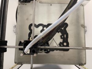
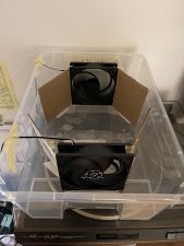
During the making there were several issues, first of all, there were problems in the code to run the rotary encoder that got fixed very quickly. Another issue to run the encoders were interrupt pins on the Arduino, which was fixed by using an Arduino Mega that has several interrupt channels. Later it turned out that the computer fans, that were bought for the prototype wouldn’t work. They turned on at a too high speed and didn’t go much higher, so they couldn’t reflect the speed from the wind and were barely able to blow any paper snippets. To solve that brushless DC motors together with ESC drivers are chosen and brought new issues. First, only one arrived and second, the power source for testing them doesn’t have a constant current which is responsible for only being able to use a higher rpm. One last big problem was that no one cooperated to 3D print the needed parts to be able to even use some functions. | During the making there were several issues, first of all, there were problems in the code to run the rotary encoder that got fixed very quickly. Another issue to run the encoders were interrupt pins on the Arduino, which was fixed by using an Arduino Mega that has several interrupt channels. Later it turned out that the computer fans, that were bought for the prototype wouldn’t work. They turned on at a too high speed and didn’t go much higher, so they couldn’t reflect the speed from the wind and were barely able to blow any paper snippets. To solve that brushless DC motors together with ESC drivers are chosen and brought new issues. First, only one arrived and second, the power source for testing them doesn’t have a constant current which is responsible for only being able to use a higher rpm. One last big problem was that no one cooperated to 3D print the needed parts to be able to even use some functions. | ||
[[File:3D Print.jpg| 300px]] | [[File:3D Print.jpg| 300px]] | ||
[[File:Computer Fans.jpg| | [[File:Computer Fans.jpg|169px]] | ||
==Conceptual and technical changes== | |||
===Conceptual and technical changes=== | |||
During the process many aspecs have changed, e.g. from the use of computer fans it resulted that they are not precise yet not strong enough to blow away paper snippets. Then, at some point the project had too many layers and had to be simplified, so the process of printing information about air quality on receipt paper was too complicated to realise, but also to understand, so it had to be removed. At the same time it wouldn't contrubute much to the meaning. | During the process many aspecs have changed, e.g. from the use of computer fans it resulted that they are not precise yet not strong enough to blow away paper snippets. Then, at some point the project had too many layers and had to be simplified, so the process of printing information about air quality on receipt paper was too complicated to realise, but also to understand, so it had to be removed. At the same time it wouldn't contrubute much to the meaning. | ||
==Learning Process== | ===Learning Process=== | ||
The aim was to improve my skills in Arduino and working with different sensors a lot more. At the same time I was interested in the forces of nature how they can have an impact to a process or control a machine which for us seems random yet has beautiful patterns. It helped me understand to work with nature. During the class I got more interested in sound, which I didn't use in this project, but helped me for others. | The aim was to improve my skills in Arduino and working with different sensors a lot more. At the same time I was interested in the forces of nature how they can have an impact to a process or control a machine which for us seems random yet has beautiful patterns. It helped me understand to work with nature. During the class I got more interested in sound, which I didn't use in this project, but helped me for others. | ||
==Next steps== | |||
===Next steps=== | |||
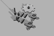
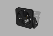
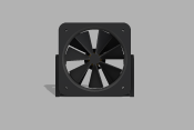
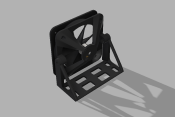
In the next steps, the 3D parts will be printed, assembled and tested. After that, the power sources will be changed to RC batteries and the receipt printer will be implemented. The incremental rotary encoder will be replaced by an absolute rotary encoder to be able to read the exact position instead of counting steps. When all this is working the box and glass cube is built and air quality sensors can be added to the setting. | In the next steps, the 3D parts will be printed, assembled and tested. After that, the power sources will be changed to RC batteries and the receipt printer will be implemented. The incremental rotary encoder will be replaced by an absolute rotary encoder to be able to read the exact position instead of counting steps. When all this is working the box and glass cube is built and air quality sensors can be added to the setting. | ||
[[File:3D Parts.png|175px]] | |||
File:3D Parts.png | [[File:FAN ASSEMBLY1.png|175px]] | ||
File:FAN ASSEMBLY1.png | [[File:FAN ASSEMBLY2.png|175px]] | ||
File:FAN ASSEMBLY2.png | [[File:FAN ASSEMBLY3.png|175px]] | ||
File:FAN ASSEMBLY3.png | |||
==Prototypes== | ==Prototypes== | ||
===Old Prototype without ball bearings and cardboard only=== | |||
[[File:Prototype1-1.jpeg|230px]] | |||
[[File:Prototype1-2.jpg|230px]] | |||
[[File:Prototype1-3.jpeg|230px]] | |||
===Newer Prototype made from a more solid material, with ball bearings and works/looks more like it will in the final result=== | |||
[[File:Prototype2-1.jpg|350px]][[File:Prototype2-2.jpg|350px]] | [[File:Prototype2-1.jpg|350px]][[File:Prototype2-2.jpg|350px]] | ||
[[File:ScreenWindThing.jpg|700px]] | [[File:ScreenWindThing.jpg|700px]] | ||
===Code to this point (can also be found on GitHub)=== | |||
https://github.com/nk246/anemometer/tree/Anenometer | https://github.com/nk246/anemometer/tree/Anenometer | ||
<source style="border:none; height:650px; overflow:scroll;" lang="c" line start="55" highlight="4"> | <source style="border:none; height:650px; overflow:scroll;" lang="c" line start="55" highlight="4"> | ||
| Line 281: | Line 281: | ||
fan_Control(); | fan_Control(); | ||
} | } | ||
| Line 420: | Line 416: | ||
==Experiments== | |||
=Experiments= | |||
===Accelerometer Experiments=== | ===Accelerometer Experiments=== | ||
| Line 533: | Line 527: | ||
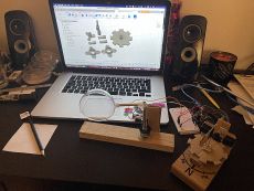
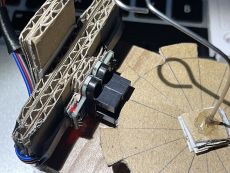
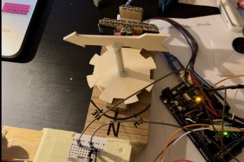
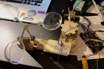
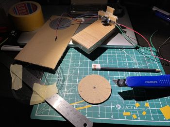
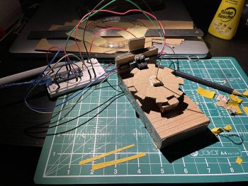
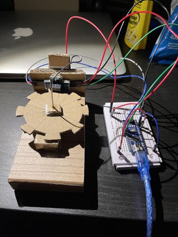
In this experiment I built an eight step rotary encoder with photo interrupters. It is used to read forward and backward steps. With these data I am able to read a direction, in my case, the direction the wind is blowing. | In this experiment I built an eight step rotary encoder with photo interrupters. It is used to read forward and backward steps. With these data I am able to read a direction, in my case, the direction the wind is blowing. | ||
{{#ev:vimeo|656531077}} | {{#ev:vimeo|656531077}} | ||
[[File:rotary1.JPG|350px]][[File:rotary2.JPG|350px]][[File:rotary3.JPG|350px]][[File:rotary4.JPG|350px]] | |||
File:rotary1.JPG | |||
File:rotary2.JPG | |||
File:rotary3.JPG | |||
File:rotary4.JPG | |||
First Code (not working properly at this stage) | ===First Code (not working properly at this stage)=== | ||
<source style="border:none; height:650px; overflow:scroll;" lang="c" line start="55" highlight="4"> | <source style="border:none; height:650px; overflow:scroll;" lang="c" line start="55" highlight="4"> | ||
| Line 658: | Line 646: | ||
Inspired by the yearly happening Sisyphean task of sweeping leaves and get them blown away again by the wind. In this installation wind is captured outdoors and will be transmitted and reproduced in a round room. Multiple fans are blowing receipts through a room in the direction and the speed from the wind outside. The fans are aligned in a circle, which reflects the pattern in which the wind is captured. The receipts are printed with nonsense information, which on one hand represent the leaves, but also address the issue of a senseless environmental pollution. | Inspired by the yearly happening Sisyphean task of sweeping leaves and get them blown away again by the wind. In this installation wind is captured outdoors and will be transmitted and reproduced in a round room. Multiple fans are blowing receipts through a room in the direction and the speed from the wind outside. The fans are aligned in a circle, which reflects the pattern in which the wind is captured. The receipts are printed with nonsense information, which on one hand represent the leaves, but also address the issue of a senseless environmental pollution. | ||
===Technical=== | |||
To capture the wind speed and and the direction, a DIY anemometer is built. For both, photo interrupters are used. To measure the wind speed, a slotted disk is used to measure the amount of steps (on/off) in a certain time and then calculated to rpm, which will be send to control the speed of the fans. For capturing the direction, a rotary encoder is built with two photo interrupters and also a disk, that has eight steps (for eight wind directions). | To capture the wind speed and and the direction, a DIY anemometer is built. For both, photo interrupters are used. To measure the wind speed, a slotted disk is used to measure the amount of steps (on/off) in a certain time and then calculated to rpm, which will be send to control the speed of the fans. For capturing the direction, a rotary encoder is built with two photo interrupters and also a disk, that has eight steps (for eight wind directions). | ||
| Line 666: | Line 654: | ||
In this class only a small scale prototype is built, with computer fans. | In this class only a small scale prototype is built, with computer fans. | ||
[[ | [[File:rotary1.JPG|350px]] | ||
Next steps: get the rotary encoder working, with interrupts and roll-overs, get the "tachometer" working and connect them to computer fans, to control them. | Next steps: get the rotary encoder working, with interrupts and roll-overs, get the "tachometer" working and connect them to computer fans, to control them. | ||
Latest revision as of 22:26, 8 February 2022
Concept
What is it?
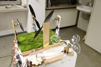
In this installation wind is captured outdoors, then transmitted and reproduced in a hermetic like glass cube right underneath. Receipt paper is slowly intruded into the space and blown by four fans, in the direction and the speed from the wind outside. To cover the whole room the fans are positioned in the corners, instead the corners would be left out and paper would get stuck. The uselessness of the reproduction of wind in the same direction, the same speed and at the exact same spot, just in an enclosed and isolated space . Like in a museum or a zoo the wind can be observed, but what can we learn from it? Is the wind an old relict that is worth to be presented in a museum? Or is the wind, like a fish in a fishtank, something that needs to be kept alive? Furthermore, this installation will be split into two parts, so it can be presented in two different contexts. The first one is for public art, the wind is, as described above reproduced live and at the exact same spot. Then, the second part would be presented in a gallery or other indoor exhibition spaces like a museum. For this case the data from part one is written on an SD card and then in the gallery recalled and played on the fans. This would be the exact echo or memory of the wind that was once there, but isn't anymore.
Technical
To capture the wind speed and and the direction, a DIY anemometer is built. For both, photo interrupters are used. To measure the wind speed, a slotted disk is used to measure the amount of steps (on/off) in a certain time and then calculated to rpm, which will be send to control the speed of the fans. For capturing the direction, a rotary encoder is built with two photo interrupters and also a disk, that has eight on and eight off steps (for eight wind directions).
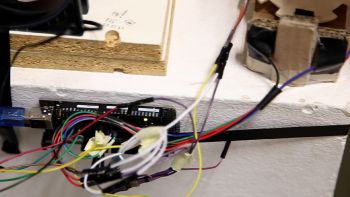
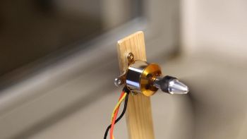
The use of an Arduino Mega is necessary to provide enough digital inputs that support interrupts, but also enough outputs for the motor controllers. For the fans, brushless motors are used, that are also very common in drones, e-bikes, etc. They are controlled with ESC motor drivers and powered by RC batteries, so the installation can stand independently from a power socket.
Aesthetics
It is all happening in a hermetic like glass cube that is sitting on a plinth. The parts are 3D printed to look neat and integrate into the installation, but still the DIY aesthetics should come out. In the cube a layer of moss is placed which on one hand is representing nature, but is also a great natural air filter. In the center on the top of the inside there is an extruder to feed the box with paper, the paper is used as an indicator for the wind and at the same time it's interesting to see what happens when the box gets slowly filled with the paper. The DIY sensors can be seen inside a transparent box that is sitting on top of the cube, so people can see what exactly is happening and can relate to the things happening inside the box.
During the process
Issues
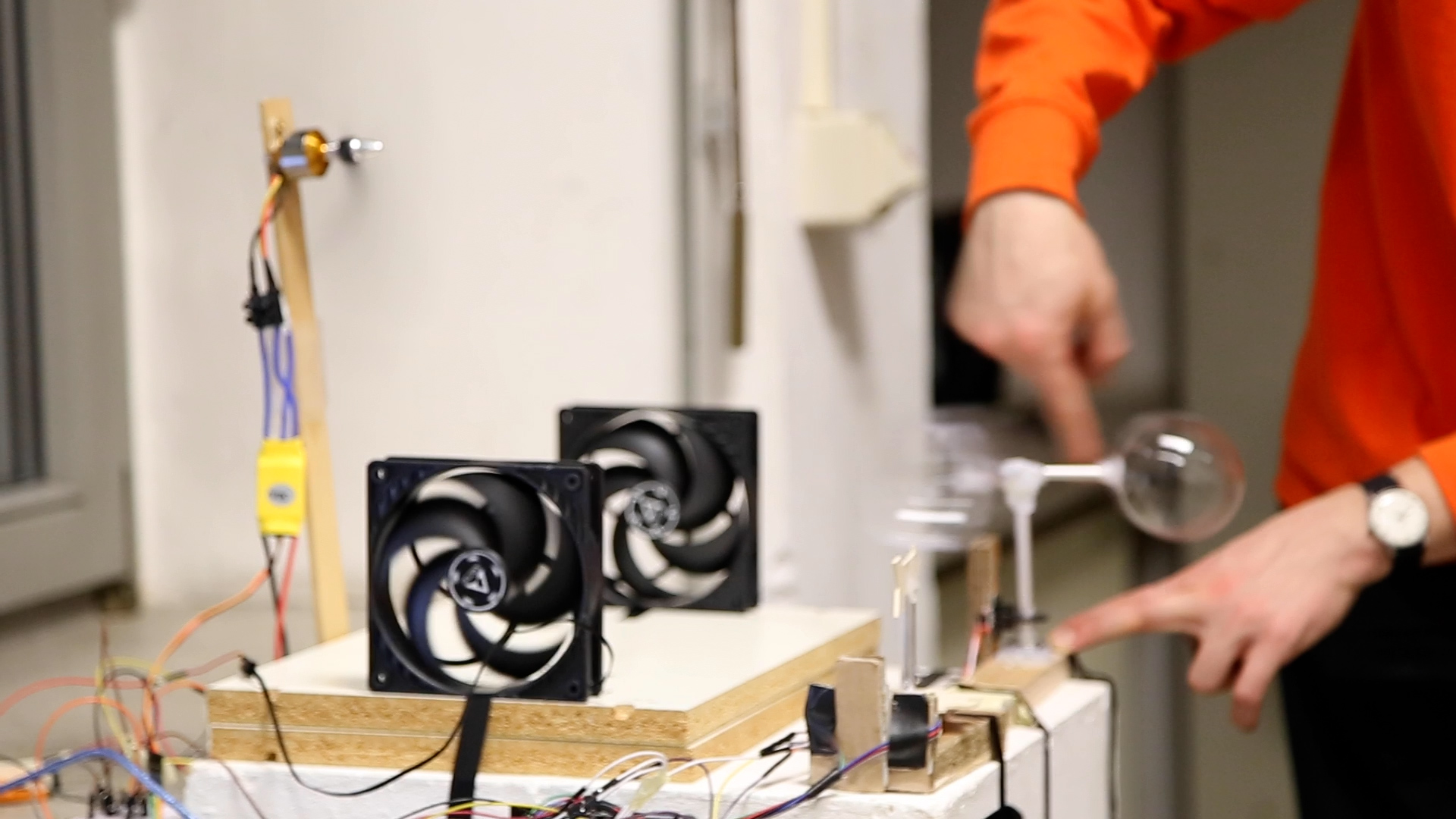
During the making there were several issues, first of all, there were problems in the code to run the rotary encoder that got fixed very quickly. Another issue to run the encoders were interrupt pins on the Arduino, which was fixed by using an Arduino Mega that has several interrupt channels. Later it turned out that the computer fans, that were bought for the prototype wouldn’t work. They turned on at a too high speed and didn’t go much higher, so they couldn’t reflect the speed from the wind and were barely able to blow any paper snippets. To solve that brushless DC motors together with ESC drivers are chosen and brought new issues. First, only one arrived and second, the power source for testing them doesn’t have a constant current which is responsible for only being able to use a higher rpm. One last big problem was that no one cooperated to 3D print the needed parts to be able to even use some functions.
Conceptual and technical changes
During the process many aspecs have changed, e.g. from the use of computer fans it resulted that they are not precise yet not strong enough to blow away paper snippets. Then, at some point the project had too many layers and had to be simplified, so the process of printing information about air quality on receipt paper was too complicated to realise, but also to understand, so it had to be removed. At the same time it wouldn't contrubute much to the meaning.
Learning Process
The aim was to improve my skills in Arduino and working with different sensors a lot more. At the same time I was interested in the forces of nature how they can have an impact to a process or control a machine which for us seems random yet has beautiful patterns. It helped me understand to work with nature. During the class I got more interested in sound, which I didn't use in this project, but helped me for others.
Next steps
In the next steps, the 3D parts will be printed, assembled and tested. After that, the power sources will be changed to RC batteries and the receipt printer will be implemented. The incremental rotary encoder will be replaced by an absolute rotary encoder to be able to read the exact position instead of counting steps. When all this is working the box and glass cube is built and air quality sensors can be added to the setting.
Prototypes
Old Prototype without ball bearings and cardboard only
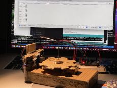
Newer Prototype made from a more solid material, with ball bearings and works/looks more like it will in the final result
Code to this point (can also be found on GitHub)
https://github.com/nk246/anemometer/tree/Anenometer
#include <Wire.h>
#include <Servo.h>

//Wind Speed
float rpm = 0;

int pid;
unsigned long millisBefore;
volatile int holes;


//Wind Direction
int sensorA; //Encoder Photo Interrupter 1
int sensorB; //Encoder Photo Interrupter 2

int stepOld;
int step;
int counter;

long PulseCount;

#define SENSOR_A 3
#define SENSOR_B 2


//FanControl
int fanN;
int fanE;
int fanS;
int fanW;

Servo EscN;
Servo EscE;
Servo EscS;
Servo EscW;

int fanSpeed;

//Checking/Comparing sensor state for wind direction
void checkState(){
  sensorA = digitalRead(SENSOR_A);
  sensorB = digitalRead(SENSOR_B);

  if(sensorA == 1 && sensorB == 1){
    step = 0;
    if(stepOld == 1){
      PulseCount--;
    }
    if(stepOld == 3){
      PulseCount++;
    }
    stepOld = 0;
  }

  if(sensorA == 0 && sensorB == 1){
    step = 1;
    if(stepOld == 2){
      PulseCount--;
    }
    if(stepOld == 0){
      PulseCount++;
    }
    stepOld = 1;
  }

  if(sensorA == 0 && sensorB== 0){
    step = 2;
    if(stepOld == 3){
      PulseCount--;
    }
    if(stepOld == 1){
      PulseCount++;
    }
    stepOld = 2;
  }

  if(sensorA == 1 && sensorB == 0){
    step = 3;
    if(stepOld == 0){
      PulseCount--;
    }
    if(stepOld == 2){
      PulseCount++;
    }
    stepOld = 3;
  }

}


void setup() {

  Serial.begin(115200);
  Serial.print("                ");
  Serial.print("                ");

  //Direction
  attachInterrupt(0, checkState, CHANGE);
  attachInterrupt(1, checkState, CHANGE);

  PulseCount = 0;

  //Speed
  pinMode (20, INPUT);
  attachInterrupt (digitalPinToInterrupt(20), count, FALLING);
  delay(1000);

  //DC-Motor start
  EscN.attach(6,1000,2000);
  EscE.attach(9,1000,2000);
  EscS.attach(10,1000,2000);
  EscW.attach(11,1000,2000);

}

void loop() {

  //Limits number of steps to 32 and if minus jumps back to
  if (PulseCount > 31) {
      PulseCount = 0;
    }

    if (PulseCount < 0) {
      PulseCount = 31;
    }

  //Switch-case for wind direction
  Serial.print("Wind-direction :  ");

  switch (PulseCount) {

    case 31:
    case 0:
    case 1:
    case 2:
    Serial.println("NORTH");
    counter = 1;
    break;

    case 3:
    case 4:
    case 5:
    case 6:
    Serial.println("NORTH-EAST");
    counter = 2;
    break;

    case 7:
    case 8:
    case 9:
    case 10:
    Serial.println("EAST");
    counter = 3;
    break;

    case 11:
    case 12:
    case 13:
    case 14:
    Serial.println("SOUTH-EAST");
    counter = 4;
    break;

    case 15:
    case 16:
    case 17:
    case 18:
    Serial.println("SOUTH");
    counter = 5;
    break;

    case 19:
    case 20:
    case 21:
    case 22:
    Serial.println("SOUTH-WEST");
    counter = 6;
    break;

    case 23:
    case 24:
    case 25:
    case 26:
    Serial.println("WEST");
    counter = 7;
    break;

    case 27:
    case 28:
    case 29:
    case 30:
    Serial.println("NORTH-WEST");
    counter = 8;
    break;
  }

  serial_Print();

  if (millis() - millisBefore > 1000) {
    rpm = (holes / 12.0) * 60;
    holes = 0;
    millisBefore = millis();
  }
  delay(500);


  fan_Control();
}

//Print Wind Speed
void serial_Print() {
  Serial.print("Wind-speed   : ");
  Serial.print(rpm);
  Serial.println(" RPM");
  Serial.println("     ");
}

//Speed Hole Count
void count() {
  holes++;
}

//Fan Control
void fan_Control() {

  fanSpeed = map(rpm, 0, 400, 0, 60); //Mapping fan speed

  switch (counter) {

    case 1:
    fanN = fanSpeed;
    EscN.write(fanN);

    EscE.write(0);
    EscS.write(0);
    EscW.write(0);

    Serial.print("FanN:  ");
    Serial.println(fanN);
    break;

    case 2:
    fanN = fanSpeed/2;
    fanE = fanSpeed/2;
    EscN.write(fanN);
    EscE.write(fanE);

    EscS.write(0);
    EscW.write(0);

    Serial.print("FanN:  ");
    Serial.println(fanN);
    Serial.print("FanE:  ");
    Serial.println(fanE);
    break;

    case 3:
    fanE = fanSpeed;
    EscE.write(fanE);

    EscS.write(0);
    EscW.write(0);
    EscN.write(0);

    Serial.print("FanE:  ");
    Serial.println(fanE);
    break;

    case 4:
    fanE = fanSpeed/2;
    fanS = fanSpeed/2;
    EscE.write(fanE);
    EscS.write(fanS);

    EscW.write(0);
    EscN.write(0);

    Serial.print("FanE:  ");
    Serial.println(fanE);
    Serial.print("FanS:  ");
    Serial.println(fanS);
    break;

    case 5:
    fanS = fanSpeed;
    EscS.write(fanS);

    EscW.write(0);
    EscN.write(0);
    EscE.write(0);

    Serial.print("FanS:  ");
    Serial.println(fanS);
    break;

    case 6:
    fanS = fanSpeed/2;
    fanW = fanSpeed/2;
    EscS.write(fanS);
    EscW.write(fanW);

    EscN.write(0);
    EscE.write(0);

    Serial.print("FanS:  ");
    Serial.println(fanS);
    Serial.print("FanW:  ");
    Serial.println(fanW);
    break;

    case 7:
    fanW = fanSpeed;
    EscW.write(fanW);

    EscN.write(0);
    EscE.write(0);
    EscS.write(0);

    Serial.print("FanW:  ");
    Serial.println(fanW);
    break;

    case 8:
    fanW = fanSpeed/2;
    fanN = fanSpeed/2;
    EscW.write(fanW);
    EscN.write(fanN);

    EscE.write(0);
    EscS.write(0);

    Serial.print("FanW:  ");
    Serial.println(fanW);
    Serial.print("FanN:  ");
    Serial.println(fanN);
    break;

  }
}
Experiments
Accelerometer Experiments
In my first experiment, I used an accelerometer to measure a specific angle on the X, Y and Z axes. I thought that it could be useful to capture the wind direction, but seemed a bit boring then.
#include <Wire.h>
#include <LiquidCrystal.h>

LiquidCrystal lcd(12, 11, 7, 8, 9, 10); // RS, E, D4, D5, D6, D7

int ADXL345 = 0x53;

float X_out, Y_out, Z_out;
float roll,pitch,rollX,pitchY,rollF,pitchF=0;


void setup() {

  //initialise tilt sensor
  Serial.begin(9600);
  Wire.begin();
  Wire.beginTransmission(ADXL345);
  Wire.write(0x2D);
  Wire.write(8);
  Wire.endTransmission();
  delay(100);

  //X-axis cal
  Wire.beginTransmission(ADXL345);
  Wire.write(0x1E);  // X-axis offset register
  Wire.write(1);
  Wire.endTransmission();
  delay(100);


  //Y-axis cal
  Wire.beginTransmission(ADXL345);
  Wire.write(0x1F); // Y-axis offset register
  Wire.write(-2);
  Wire.endTransmission();
  delay(100);


  //Z-axis cal
  Wire.beginTransmission(ADXL345);
  Wire.write(0x20); // Z-axis offset register
  Wire.write(-2);
  Wire.endTransmission();
  delay(100);

}

void loop() {
  Wire.beginTransmission(ADXL345);
  Wire.write(0x32);
  Wire.endTransmission(false);
  Wire.requestFrom(ADXL345, 6, true);
  X_out = ( Wire.read() | Wire.read() << 8);
  X_out = X_out/256;
  Y_out = ( Wire.read() | Wire.read() << 8);
  Y_out = Y_out/256;
  Z_out = ( Wire.read() | Wire.read() << 8);
  Z_out = Z_out/256;

  Serial.println("RAW: ");
  Serial.print("Xa= ");
  Serial.print(X_out);
  Serial.print("   Ya= ");
  Serial.print(Y_out);
  Serial.print("   Za= ");
  Serial.println(Z_out);
  Serial.println("  ");
  delay(200);

  roll = atan(Y_out / sqrt(pow(X_out, 2) + pow(Z_out, 2))) * 180 / PI;
  pitch = atan(-1 * X_out / sqrt(pow(Y_out, 2) + pow(Z_out, 2))) * 180 / PI;
  // Low-pass filter
  rollX = 0.94 * rollX + 0.06 * roll;
  pitchY = 0.94 * pitchY + 0.06 * pitch;

  lcd.begin(8, 2);
  lcd.print("X: ");
  lcd.print(rollX+6, 0);
  lcd.write((char)0b11011111);
  lcd.setCursor(0,1);
  lcd.print("Y: ");
  lcd.print(pitchY+1, 0);
  lcd.write((char)0b11011111);
  delay(200);

  Serial.println("FINAL: ");
  Serial.print("X: ");
  Serial.print(rollX+6, 0);
  Serial.print("˚");
  Serial.print("    Y: ");
  Serial.print(pitchY+1, 0);
  Serial.println("˚");
  Serial.println("–––––––––––––––––––––––––––––––––––––––");
  delay(200);
}
Rotary Encoder
In this experiment I built an eight step rotary encoder with photo interrupters. It is used to read forward and backward steps. With these data I am able to read a direction, in my case, the direction the wind is blowing.
First Code (not working properly at this stage)
int sensorA;
int sensorB;

int stepOld;
int step;

long PulseCount;

#define SENSOR_A 4
#define SENSOR_B 2

void checkState(){
  sensorA = digitalRead(SENSOR_A);
  sensorB = digitalRead(SENSOR_B);

  if(sensorA == 1 && sensorB == 1){
    step = 0;
    if(stepOld == 1){
      PulseCount--;
    }
    if(stepOld == 3){
      PulseCount++;
    }
    stepOld = 0;
  }

  if(sensorA == 0 && sensorB == 1){
    step = 1;
    if(stepOld == 2){
      PulseCount--;
    }
    if(stepOld == 0){
      PulseCount++;
    }
    stepOld = 1;
  }

  if(sensorA == 0 && sensorB== 0){
    step = 2;
    if(stepOld == 3){
      PulseCount--;
    }
    if(stepOld == 1){
      PulseCount++;
    }
    stepOld = 2;
  }

  if(sensorA == 1 && sensorB == 0){
    step = 3;
    if(stepOld == 0){
      PulseCount--;
    }
    if(stepOld == 2){
      PulseCount++;
    }
    stepOld = 3;
  }

}

void setup() {

  Serial.begin(115200);
  Serial.print("                ");
  Serial.print("                ");

  attachInterrupt(0, checkState, CHANGE);
  attachInterrupt(1, checkState, CHANGE);

  PulseCount = 0;
}

void loop() {
  Serial.print("Steps:");
  if(PulseCount > -1){
    Serial.print(" ");
  }

  if(PulseCount < 10 && PulseCount > -10){
    Serial.print(" ");
  }

  if(PulseCount < 100 && PulseCount > -100){
    Serial.print(" ");
  }

  Serial.print(PulseCount);
  if(sensorA == 1){
    Serial.println("  HIGH");
  }
  else{
    Serial.println("  LOW ");
  }

  if(sensorB == 1){
    Serial.println("            HIGH");
  }
  else{
    Serial.println("            LOW ");
  }

}
Old concept sketch
Inspired by the yearly happening Sisyphean task of sweeping leaves and get them blown away again by the wind. In this installation wind is captured outdoors and will be transmitted and reproduced in a round room. Multiple fans are blowing receipts through a room in the direction and the speed from the wind outside. The fans are aligned in a circle, which reflects the pattern in which the wind is captured. The receipts are printed with nonsense information, which on one hand represent the leaves, but also address the issue of a senseless environmental pollution.
Technical
To capture the wind speed and and the direction, a DIY anemometer is built. For both, photo interrupters are used. To measure the wind speed, a slotted disk is used to measure the amount of steps (on/off) in a certain time and then calculated to rpm, which will be send to control the speed of the fans. For capturing the direction, a rotary encoder is built with two photo interrupters and also a disk, that has eight steps (for eight wind directions).
In the final result, the use of an Arduino Mega is necessary to provide enough digital inputs that support interrupts, but also enough outputs for the fans. For the fans, brushless motors are used, that are also very common in drones, e-bikes, etc. They are controlled with motor drivers and powered by a power supply unit.
In this class only a small scale prototype is built, with computer fans.
Next steps: get the rotary encoder working, with interrupts and roll-overs, get the "tachometer" working and connect them to computer fans, to control them.
