No edit summary |
No edit summary |
||
| (One intermediate revision by the same user not shown) | |||
| Line 127: | Line 127: | ||
''Two forms on Jeans and cotton cloth'' | ''Two forms on Jeans and cotton cloth'' | ||
[[File: | [[File:loudspeakerayla6.jpg]]<br><br> | ||
''Coloured conductive ink'' | ''Coloured conductive ink'' | ||
Latest revision as of 12:46, 7 January 2016
SOME BASICS
ASSIGNMENT 1 - IMPROBABLE SWITCH
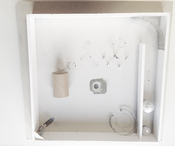
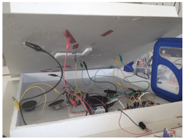
Aline and me decided to make a"simple pinball switches" in a box.
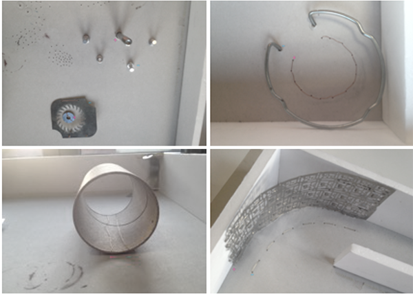
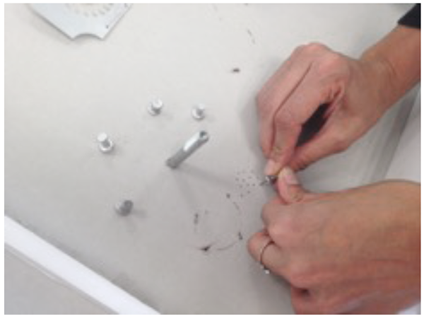
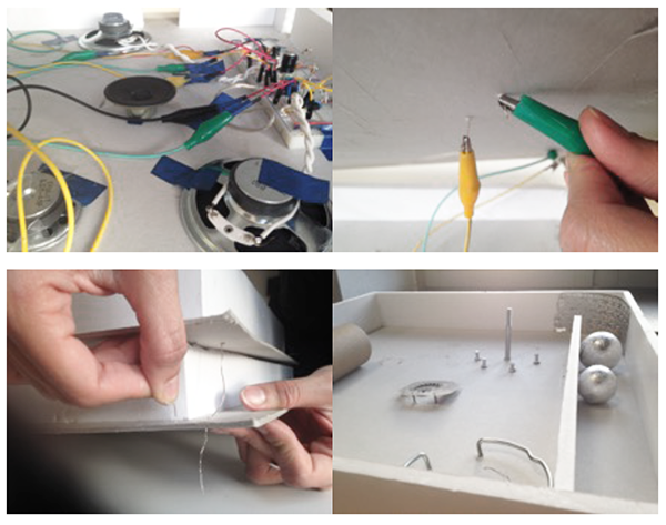
We went through some trash bins on the campus and found some thicker cardboard boxes, probably used by architecture students. We also found some conductive materials that were our six obstacles aka our six switches. Between the two cardboard boxes we put two breadboards that were creating five sounds. With the help of some alligator clips we connected every obstacle on the inner side with some copper wire to the breadboards.
So each obstacle was one part of the switch. The circuit was closed when the ball that was wrapped in aluminium foil touched the positive and the negative part of the obstacle.
Because the speakers were inside the box, the sounds were a bit silent so we made some holes on the sides of the box and also some smaller ones on the board itself.
While building we realized that it's always that you have to think about how to attach something to another part, make it stiff or make it flexible, also.
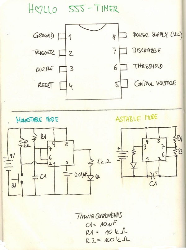
Inside the machine, we worked with five 555 timers in two different breadboards.
The main constructions was the same but the values were varying in relation to different values of the resistors between the pins 6-7 and 7-8 and the capacitors between pins 1-2 and 3.
Circuits: 1 ) R2 : 1 M ohm 2) R2: 10K ohm 3) R2: 100K ohm R1 : 100 K ohm R1: 10K ohm R1: 10K ohm 1 - 2 :0.1 μF 1 - 2 : 0.1 μF 1 - 2 : 0.1 μF 3: 1μF 3: 47μF 3: 100μF 4) R2 : 1K ohm 5) R2 : 10 K ohm R1 : 1 K ohm R1 : 100 K ohm 1 - 2 : 0.1μF 1 - 2 : 0.1μF 3: 22 μF 3: 47μF
ASSIGNMENT 2 - VARIABLE RESISTANCE
For the second assignment I started some research on the piezo and got interested in the fact that it doesn't work as an acoustic microphone but one that's depending on vibration.
So my attempt for the beginning was to use it as an input into the 555 circuit in monostable mode (for some reasons it did not work at all in the astable mode). So there was a permanent sound of the circuit and whenever I touched the piezo it gave some really small extra sound, pushing it harder did make it a little bit louder. Instead of the loudspeaker I used a LED to see the changes better. In this case my body was working as a variable resistance. I wanted to get a stronger signal that I could also work with. In this class and in the following last block I was occupied with researching on some amplifyer circuits.
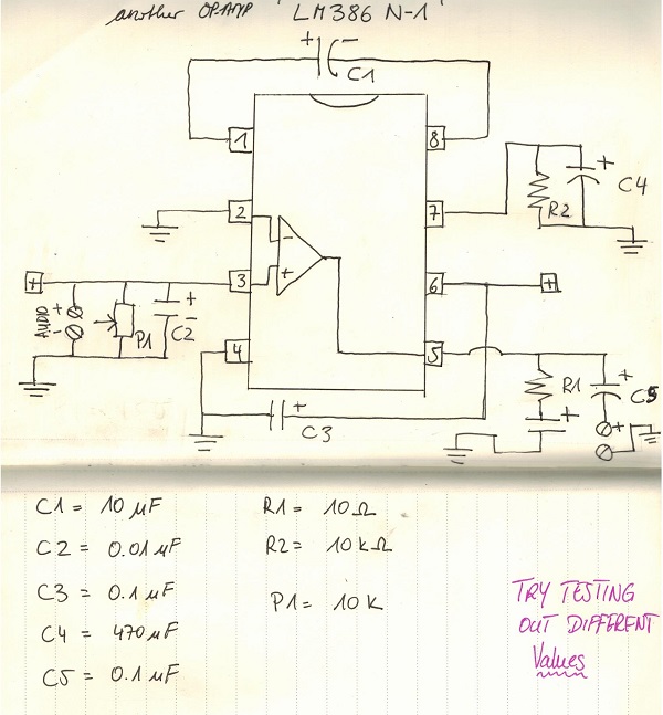
There are some different amplifyers that I came across but I kept on working with the LM385N for my piezo research. In another course I printed loudspeakers by the silkscreen printing technique for which I used the LM 386N-1.
The last OP-AMP I came across in my research is the 741, which I haven't tested already but I will add some schematics that I found online about this too.
[Brief digression 'zener diode': A zener diode helps to clamp the current voltage down to a specific voltage to protect devices from too high voltage https://de.wikipedia.org/wiki/Z-Diode]
ASSIGNMENT 3 - Detecting Vibrations
Video
Work in progress
When you google vibration (in German) the first entries you will get are about safety precautions on working spaces. It says, that their impact on people can range from disturbance and performance loss over health hazard to health damage (Institut für Arbeitsschutz der Deutschen Gesetzlichen Unfallversicherung). Vibrations are less acoustic and more about a sensory feeling. If something that you are standing on is vibrating you will feel it but you won't either see nor hear the vibrations only what's vibrating is recognizable. The phenomenon is stuck to materials. I would be intersted in de-materialising vibrations and make them noticeable on different levels. I am interested in researching more the concepts of sound and vibration which often are used in similar ways. The idea I would like to pursue is to work on an installation that reacts to vibrations sensed by piezos. It would be nice to have some closed self-fulfilling system that uses and causes vibrations. In first place I need to work on a stronger signal coming from the piezo element. Therefore I will do more experiments on different OP-AMPs and also different components that can effect the outcome.
Schematic of LM386, piezo mic as an input and a LED as the output
Experiment: Loudspeaker-Printing with Silk screen printing method
Work in progress
With conductive ink I tried to print spiral-shaped forms on textiles and paper with the silk screen printing method. It was the first time that I tried silk screen printing. The prints were acceptable but the most important point was that they should be conductive. With some ironing of the prints the conductivity got better.

Two forms on Jeans and cotton cloth
I also built an amplifiyer circuit with the LM386 and used an old headphone jack to connect my smartphone to the circuit, so that the sound that was coming from my phone could be listened to on the printed loudspeakers. It did work but really silent. Right now there are some points I need to trouble shoot but I think with some better wireing and the pure silver ink I could get better results.


