| (17 intermediate revisions by the same user not shown) | |||
| Line 5: | Line 5: | ||
---- | ---- | ||
==FINAL PROJECT: ELECTRIC | ==FINAL PROJECT: ELECTRIC MIMOSA== | ||
[[File:f01.jpg]] | |||
====I. Circuit Overview==== | ====I. Circuit Overview==== | ||
| Line 15: | Line 17: | ||
[[File:Mimosa_Pudica.gif]] | [[File:Mimosa_Pudica.gif]] | ||
'''a. | '''a. Circuit Diagram with Photocell''' | ||
[[File:f2.jpg]] | |||
====II. Circuit construction ==== | ====II. Circuit construction ==== | ||
| Line 27: | Line 27: | ||
* Flexinol (nickel - titanium wire alloy) | * Flexinol (nickel - titanium wire alloy) | ||
* | * Potentiometer 100k | ||
* Capacitor 0.1 mf | |||
* Potentiometer 100k | |||
* Photocell | |||
* Transistor TIP 120 | |||
* Diode 1n404 | |||
* Relay | |||
* LED | |||
* Resistor 1k Ohm | |||
* 2 Batteries 9 volt. | |||
'''Testing the wire video ''' | '''Testing the wire video ''' | ||
| Line 39: | Line 55: | ||
<videoflash>4onE5ArcOdc|980|500</videoflash> | <videoflash>4onE5ArcOdc|980|500</videoflash> | ||
If you can not see the video, please go to this link: https://www.youtube.com/watch?v=4onE5ArcOdc | |||
'''Testing shapes ''' | '''Testing shapes ''' | ||
[[File:EP_Sh2.JPG]] | [[File:EP_Sh2.JPG]] | ||
[[File:EP_Sh3.JPG]] | [[File:EP_Sh3.JPG]] | ||
[[File:EP_Sh4.JPG]] | [[File:EP_Sh4.JPG]] | ||
'''Circuit 1 (movement detection with photocell) ''' | |||
[[File:f3.jpg]] | |||
'''Video Circuit 1 (movement detection with photocell) ''' | |||
See the embedded video below: | |||
<videoflash>z93bIc7RSCw|980|500</videoflash> | |||
If you can not see the video, please go to this link: https://www.youtube.com/watch?v=z93bIc7RSCw | |||
'''Plant and leafs construction''' | |||
Cutting paper leafs | |||
[[File:f5.jpg]] | |||
Installing Flexinol and wire inside the leafs | |||
[[File:f6.jpg]] | |||
Assembling wire and leaves | |||
[[File:f7.jpg]] | |||
Soldering the wire between the leafs | |||
[[File:f4.jpg]] | |||
[[File:f8.jpg]] | |||
Assembling fixed leafs | |||
[[File:f9.jpg]] | |||
[[File:f10.jpg]] | |||
[[File:f11.jpg]] | |||
====III. FINAL INSTALLATION ==== | |||
Assembled Garden | |||
[[File:f12.jpg]] | |||
Electric Mimosa in a Box | |||
See the embedded video below: | |||
<videoflash>7OmGwjNY6-4|980|500</videoflash> | |||
If you can not see the video, please go to this link: https://www.youtube.com/watch?v=7OmGwjNY6-4 | |||
The magic Inside the box | |||
[[File:f13.jpg]] | |||
[[File:f14.jpg]] | |||
====IV. INSIDE OF THE ELECTRIC GARDEN ==== | |||
[[File:f15.jpg]] | |||
[[File:f15_1.jpg]] | |||
See the embedded video below: | |||
<videoflash>u6Sx-3P1HiU|980|500</videoflash> | |||
If you can not see the video, please go to this link: https://www.youtube.com/watch?v=u6Sx-3P1HiU | |||
====V. FUTURE IMPROVEMENTS ==== | |||
1. Incorporate an Infrared sender and receiver instead of a Photocell in order to improve the reaction to “touch” | |||
2. At the moment, I’m experimenting with 3D printing and a possible electronic object with this technique. These are photos of this process so far | |||
3D Model file for the printing | |||
[[File:f16.gif]] | |||
Opps! Problems with the object design... | |||
[[File:f17.jpg]] | |||
==ASSIGNMENT 2 : THE EXPERIMENTAL RESISTANCE== | ==ASSIGNMENT 2 : THE EXPERIMENTAL RESISTANCE== | ||
Latest revision as of 14:12, 15 March 2016
Assignments/Projects for GMU:The Conceptual Sensor - Winter Semester 2015.
By Vanessa Yepes Serna
FINAL PROJECT: ELECTRIC MIMOSA
I. Circuit Overview
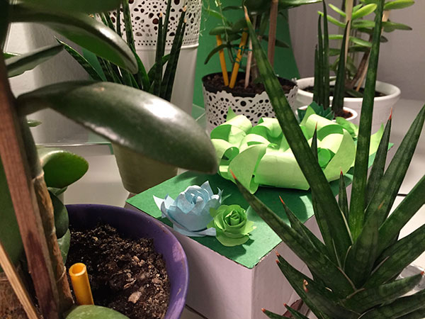
Inspired by the smooth-organic movement of the Sleepy Plant (Mimosa pudica) this circuit wants to experiment with different methods of locomotion, testing the possibilities of the nickel - titanium wire alloy.
Mimosa movement
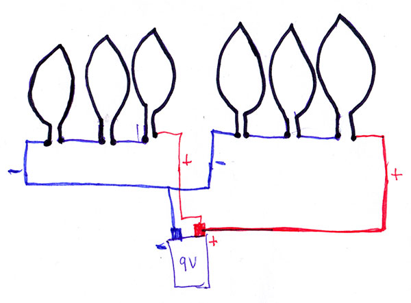
a. Circuit Diagram with Photocell
II. Circuit construction
Materials:
- Flexinol (nickel - titanium wire alloy)
- Potentiometer 100k
- Capacitor 0.1 mf
- Potentiometer 100k
- Photocell
- Transistor TIP 120
- Diode 1n404
- Relay
- LED
- Resistor 1k Ohm
- 2 Batteries 9 volt.
Testing the wire video
See the embedded video below:
<videoflash>4onE5ArcOdc|980|500</videoflash>
If you can not see the video, please go to this link: https://www.youtube.com/watch?v=4onE5ArcOdc
Testing shapes
Circuit 1 (movement detection with photocell)
Video Circuit 1 (movement detection with photocell)
See the embedded video below:
<videoflash>z93bIc7RSCw|980|500</videoflash>
If you can not see the video, please go to this link: https://www.youtube.com/watch?v=z93bIc7RSCw
Plant and leafs construction
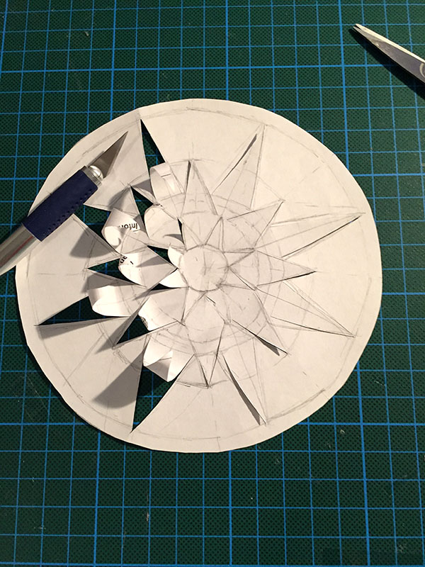
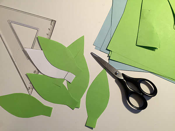
Cutting paper leafs
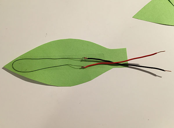
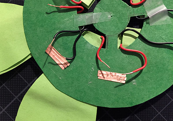
Installing Flexinol and wire inside the leafs
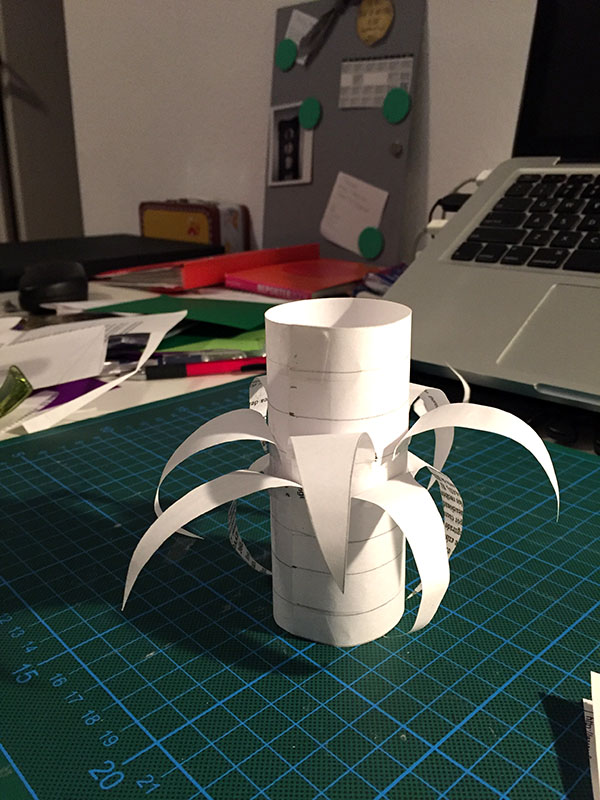
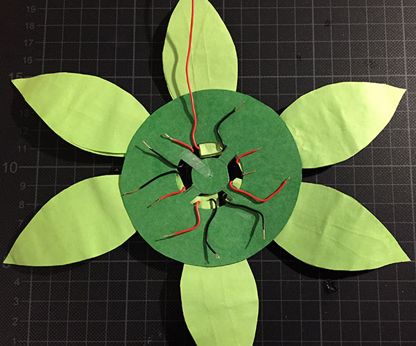
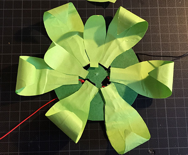
Assembling wire and leaves
Soldering the wire between the leafs
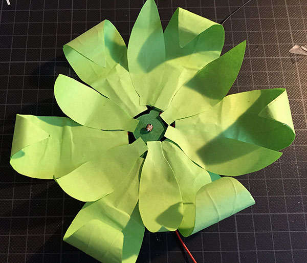
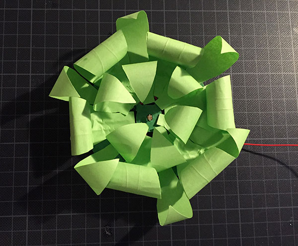
Assembling fixed leafs
III. FINAL INSTALLATION
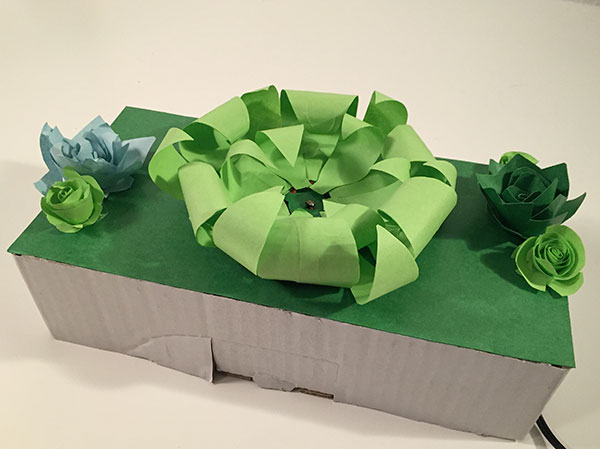
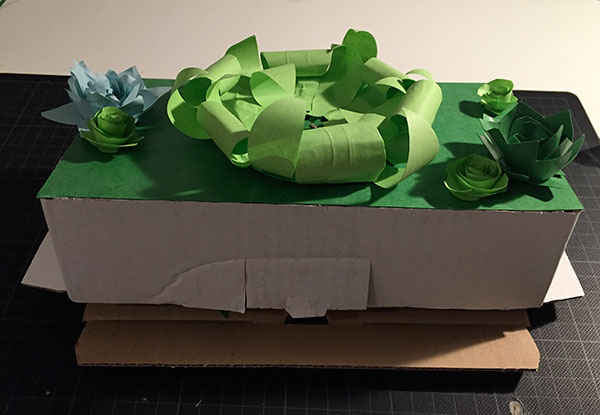
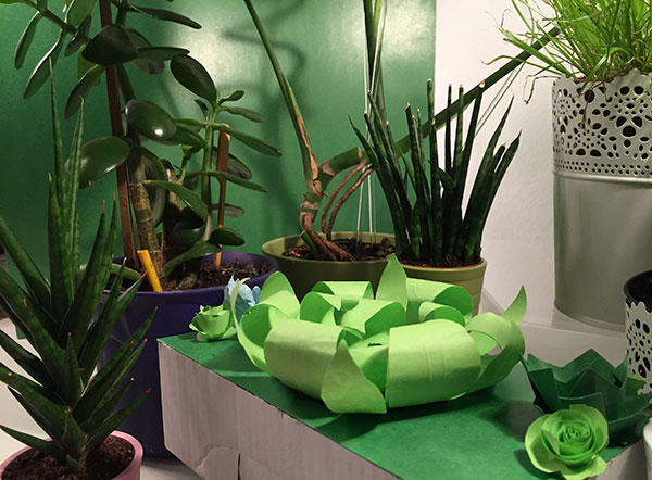
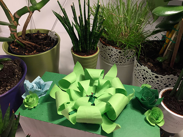
Assembled Garden
Electric Mimosa in a Box
See the embedded video below:
<videoflash>7OmGwjNY6-4|980|500</videoflash>
If you can not see the video, please go to this link: https://www.youtube.com/watch?v=7OmGwjNY6-4
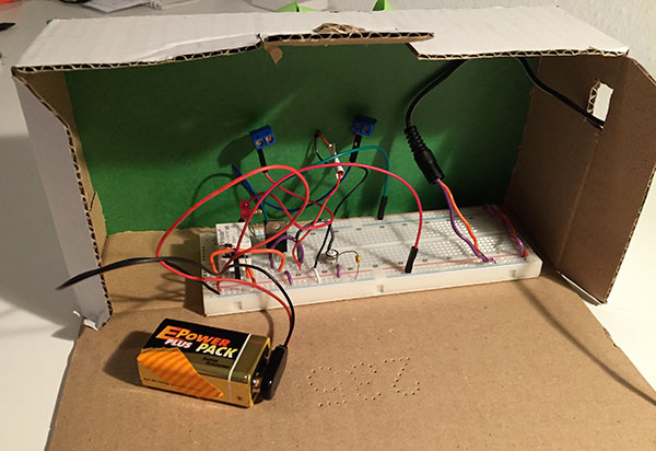
The magic Inside the box
IV. INSIDE OF THE ELECTRIC GARDEN
See the embedded video below:
<videoflash>u6Sx-3P1HiU|980|500</videoflash>
If you can not see the video, please go to this link: https://www.youtube.com/watch?v=u6Sx-3P1HiU
V. FUTURE IMPROVEMENTS
1. Incorporate an Infrared sender and receiver instead of a Photocell in order to improve the reaction to “touch”
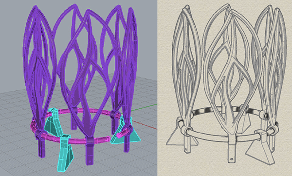
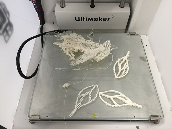
2. At the moment, I’m experimenting with 3D printing and a possible electronic object with this technique. These are photos of this process so far
3D Model file for the printing
Opps! Problems with the object design...
ASSIGNMENT 2 : THE EXPERIMENTAL RESISTANCE
I. Description
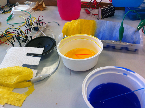
All the objects around us have its own amount of electric conductivity, some of then let the electricity runs wild and other just make it slow. This exercise is an attempt to control the flow of electric current, and show in a tangible way the electric current activity.
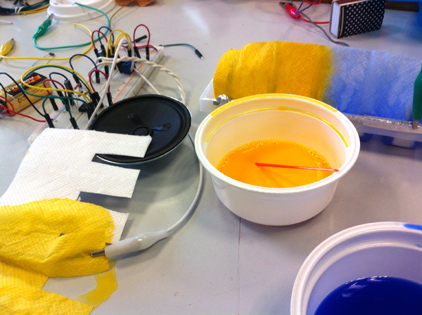
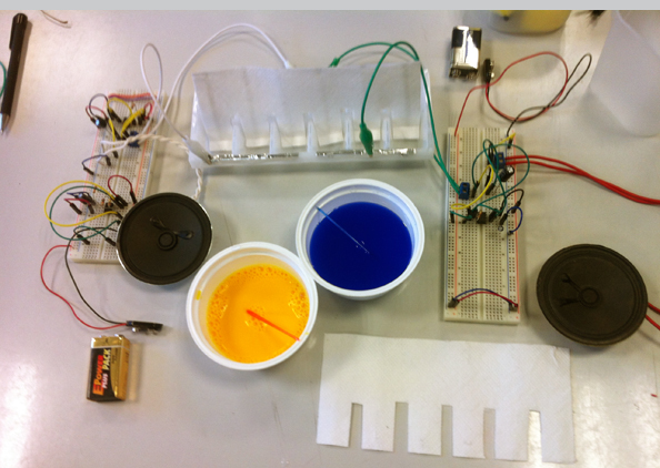
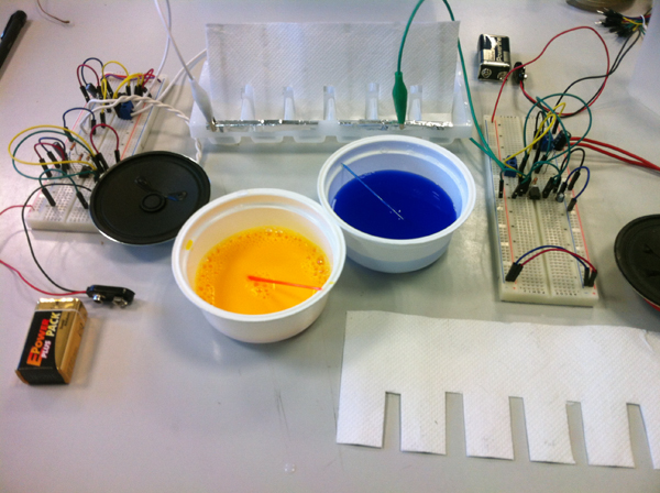
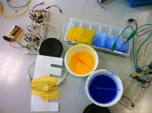
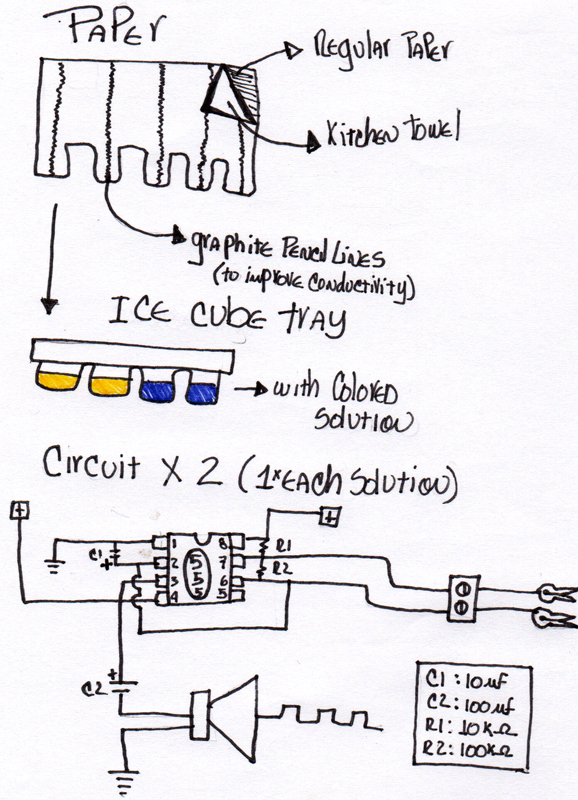
Using colored water with a dilution of different conductive materials like salt, soap and vinegar, this circuit makes different noises when the resistance of the piece of paper decreases due the amount of conductive solution in it. The result is a visual color mixing game that plays various sounds according with the ingredient diluted in the colored solution.
I. Photos
a. Before the colored solution
a. After color mixing
2. Circuit Diagram and Sketches
ASSIGNMENT 1 : THE IMPROBABLE SWITCH
I. Description
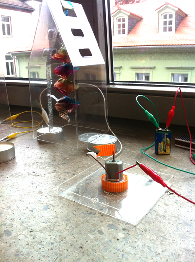
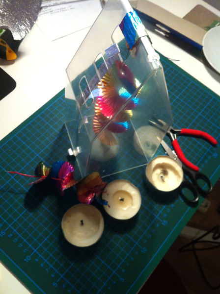
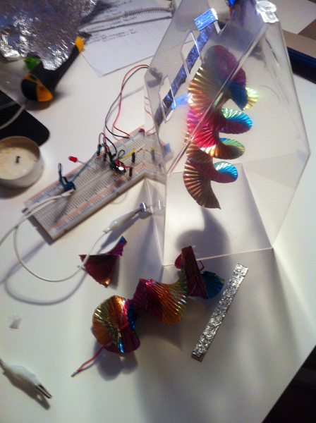
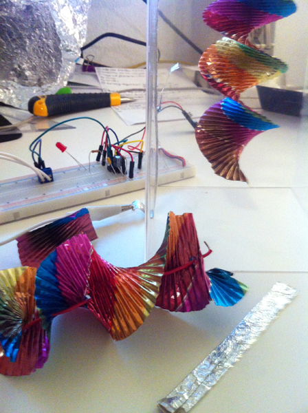
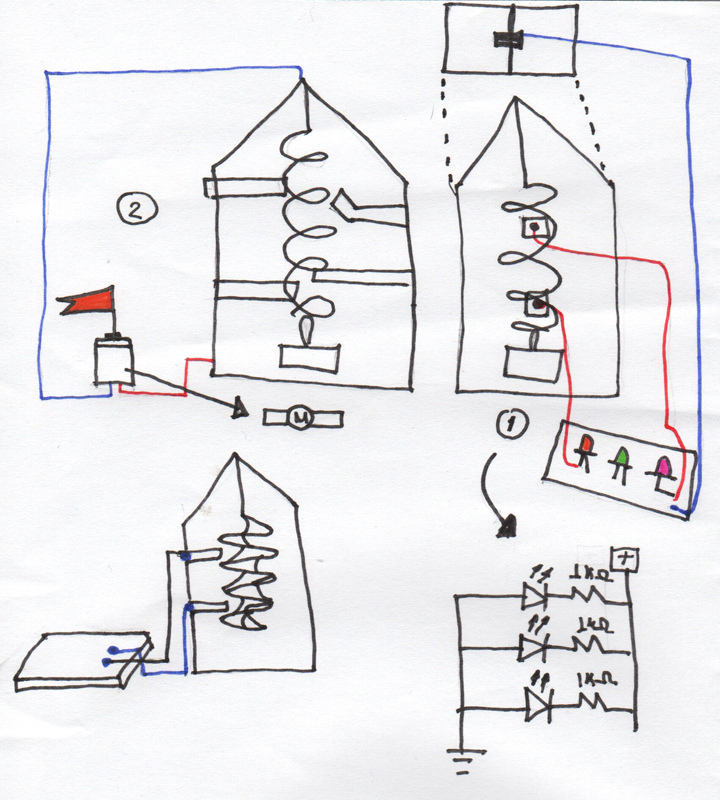
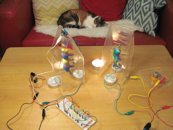
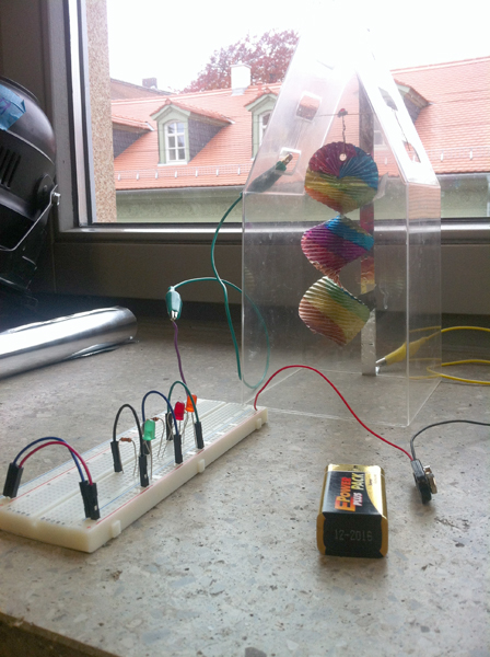
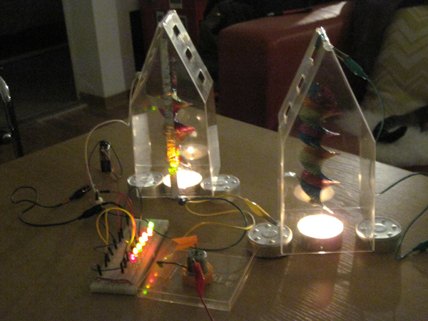
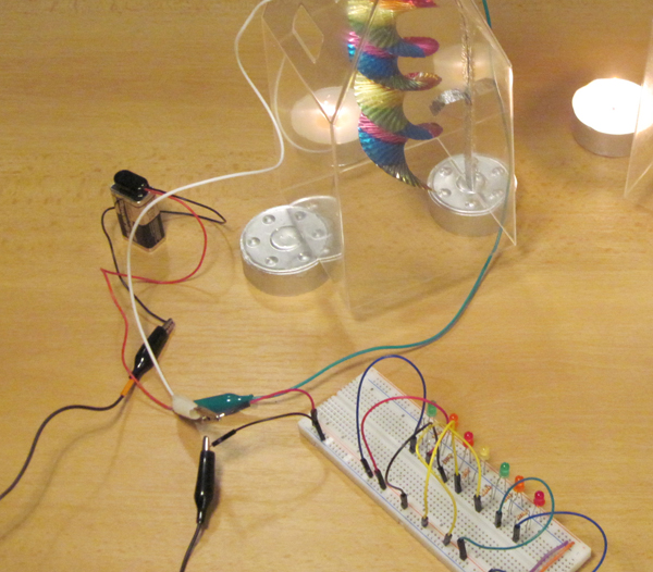
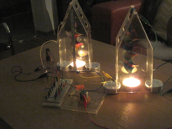
This exercise experiments with the different ways to close a circuit, any material could be a switch with the right construction with more visually interesting results than the black boxes in our daily electronic objects. In this case, a candle is used to warm the air around a metallic spiral and produce movement. When the spiral moves, it opens and closes the circuit, touching aluminum leafs installed inside of the small greenhouse. When the switch is on the little flag in the motor moves and the lights turn on.
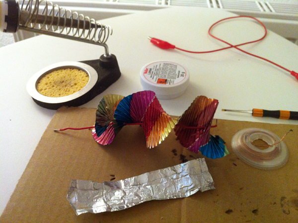
2 Construction Photos
3. Circuit Diagram and Sketches
4. Circuit Photos
5. Video
You can not see the embedded video below:
If you can see the video, please go to this link: [1]
<videoflash>Qf4I3rnYsi8|980|500</videoflash>
If you can not see the video, please go to this link: [2]
