m (→UDP sending) |
|||
| (12 intermediate revisions by the same user not shown) | |||
| Line 67: | Line 67: | ||
== using the esp8266 with software serial == | == using the esp8266 with software serial == | ||
[[File:Arduino_Pro_Mini_and_ESP-8266.png|600px]] | |||
to be tried: | to be tried: | ||
| Line 112: | Line 114: | ||
} | } | ||
} | } | ||
</source> | |||
== Use as a standalone Microcontroller Board == | |||
Installation Instructions for the Arduino IDE: https://github.com/esp8266/Arduino | |||
[[File:ESP8266_Standalone.png | 800px]] | |||
Enter Flash mode (to upload new firmware): | |||
and try to upload the example patch below: | |||
<source lang=c> | |||
/* ESP8266 as an Arduino | |||
* Wiring: | |||
* GPIO15 (IO15) to GND | |||
* CHIP Enable to VCC (on some modules: CH_PD) | |||
* GPIO0 (IO0) to GND | |||
*/ | |||
void setup() { | |||
Serial.begin(115200); | |||
} | |||
void loop() { | |||
delay(1000); | |||
Serial.println("I'm there!!!!!"); | |||
} | |||
</source> | |||
'''pin mapping:''' | |||
<source lang = c> | |||
ESP8266 PINS | |||
============ | |||
Arduino Pin 0 = IO0 | |||
Arduino Pin 1 = Blue LED | |||
Arduino Pin 2 = IO2 | |||
Arduino Pin 3 = ?? | |||
Arduino Pin 4 = IO4 | |||
Arduino Pin 5 = IO5 | |||
Arduino Pin 6 = ?? | |||
Arduino Pin 7 = ?? | |||
Arduino Pin 8 = ?? | |||
Arduino Pin 12 = IO12 | |||
Arduino Pin 13 = IO13 | |||
Arduino Pin 14 = IO14 | |||
Arduino Pin 15 = IO15 | |||
</source> | |||
== UDP sending == | |||
<source lang=c> | |||
#include <ESP8266WiFi.h> | |||
#include <ESP8266mDNS.h> | |||
#include <WiFiUdp.h> | |||
WiFiUDP udp; | |||
const char* ssid = "yourWifiName"; | |||
const char* password = "yourPassword"; | |||
const char* hostString = "yourHostName"; | |||
void setup() { | |||
Serial.begin(57600); | |||
delay(100); | |||
Serial.println("\r\nsetup()"); | |||
WiFi.hostname(hostString); | |||
WiFi.begin(ssid, password); | |||
while (WiFi.status() != WL_CONNECTED) { | |||
delay(250); | |||
Serial.print("."); | |||
} | |||
Serial.println(""); | |||
Serial.print("Connected to "); | |||
Serial.println(ssid); | |||
Serial.print("IP address: "); | |||
Serial.println(WiFi.localIP()); | |||
if (!MDNS.begin(hostString)) { | |||
Serial.println("Error setting up MDNS responder!"); | |||
} | |||
Serial.println("mDNS responder started"); | |||
} | |||
void loop() { | |||
IPAddress broadcastIp(192, 168, 0, 110); | |||
//IPAddress broadcastIp(255, 255, 255, 255); | |||
udp.beginPacket(broadcastIp,5555); | |||
udp.write("hi"); | |||
udp.endPacket(); | |||
delay(500); | |||
} | |||
</source> | |||
== Reverting Firmware to AT Firmware == | |||
This is for the esp-201 module, coming with 4mbit (512kB) flash. | |||
Get the latest Firmware on the espressif bbs home page: | |||
http://bbs.espressif.com/viewtopic.php?f=46&t=2054 | |||
(this was last checked 2016-05-10 - there might be a more up to date version now) | |||
either use the flash download tool from the above linked page or for example the very useful esptool: | |||
https://github.com/themadinventor/esptool | |||
extract the downloaded files, open a shell and change into the directory "/ESP8266_NONOS_SDK/bin" | |||
<source lang=bash> | |||
esptool.py --port /dev/ttyUSB0 write_flash 0x00000 boot_v1.2.bin 0x01000 at/512+512/user1.1024.new.2.bin 0x3e000 blank.bin 0x7e000 blank.bin | |||
</source> | |||
or for an original ai thinker firmware: | |||
download [http://bbs.espressif.com/download/file.php?id=189 esp_iot_sdk_v0.9.5_15_01_23.zip] | |||
<source lang=bash> | |||
esptool.py --port /dev/ttyUSB1 write_flash 0x00000 boot_v1.2.bin 0x01000 at/user1.512.new.bin 0x3e000 blank.bin 0x7e000 blank.bin | |||
</source> | </source> | ||
Latest revision as of 14:49, 14 June 2016
Testing and using a ESP8266 board
Electronic Setup
http://www.uni-weimar.de/medien/wiki/images/Esp-201-cheatsheet.svg
Supply the board with 3.3V on VCC, best run it with a voltage source or regulator that can at least deliver 300mA (many arduino boards have 3.3V regulators on board, but they deliver less than 300mA). Initial testes just with a ftdi usb to serial converters show unstable wifi connections, sometimes even board startup is impossible (the esp8266 board draws too much current).
Testing the Board with AT Commands
full reference of all AT commands: http://bbs.espressif.com/download/file.php?id=256
first steps:
AT+RST - resets the board:
ATE1 (verbose)
ATE0 (non verbose)
pre-setup to either join a network (station mode) or create a new network acces point (AP)
AT+CWMODE=1 station mode (join an existing wifi network)
AT+CWMODE=2 access point mode (create a new wifi network)
AT+CWMODE=3 access point mode + station mode (create a wifi and join an other one at the same time)
select a network around you and join it:
AT+CWLAP list available networks around you that you could join.
AT+CWJAP="SSID","Your Password" (join a network with the ssid (visible name) and your wifi password)
or if you don't want to join an existing network, create your own:
AT+CWSAP_DEF="GoAway!!!","myAss!!!",1,0 (creates a wifi with the name GoAway!!! and an optional password: myAss!!! on channel 1.
0 means "no encryption", so the password that was set before as myAss!!!" is not used here. (instead 0 setting to 3 uses wpa2_psk, so the password would be used)
AT+CWDHCP_DEF=1 (turn on DHCP, so others can automatically get an IP address when they connect to your wifi)
either as a station or an AP create a simple server others can connect to:
AT+CIPMUX=1 (1: server accepts multiple connection, 0: single connections only)
AT+CIPSERVER=1,80 (1: create 0:destroy server, 80: listening on port 80)
now you can try to connect to your server, eg with your browser (not a good idea, but still interesting...) we need the ip address for that.
find the ip of your esp8266 board:
AT+CIFSR (wait until you get the below output)
+CIFSR:APIP,"192.168.4.1"
+CIFSR:APMAC,"1a:fe:34:d2:47:65"
+CIFSR:STAIP,"0.0.0.0"
+CIFSR:STAMAC,"18:fe:34:d2:47:65"
The first line shows the IP address of your board. you can now enter it in a browser: http://192.168.4.1:80 other convenient tests: in the shell: telnet, netcat in puredata: netsend
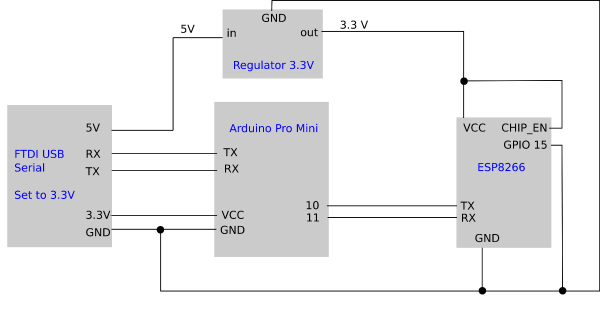
using the esp8266 with software serial
to be tried: https://github.com/itead/ITEADLIB_Arduino_WeeESP8266
simple sketch to test the software serial and the esp connected to it, based on softwareSerialExample.ino
AT+UART=9600,8,1,0,0Sets the ESP8266 to 9600 baud, 8 databits, 1 stop bit no parity bit and no flow control.
/*
 * The circuit:
 * RX is digital pin 10 (connect to TX of the ESP8266)
 * TX is digital pin 11 (connect to RX of the ESP8266)
 *
 * This example code is in the public domain.
 */

#include <SoftwareSerial.h>

SoftwareSerial mySerial(10, 11); // RX, TX

void setup() {
  // Open serial communications and wait for port to open:
  Serial.begin(57600);
  while (!Serial) {
    ; // wait for serial port to connect. Needed for native USB port only
  }


  Serial.println("Goodnight moon!");

  // set the data rate for the SoftwareSerial port
  mySerial.begin(9600);
  mySerial.println("AT+RST");
}

void loop() { // run over and over
  if (mySerial.available()) {
    Serial.write(mySerial.read());
  }
  if (Serial.available()) {
    mySerial.write(Serial.read());
  }
}
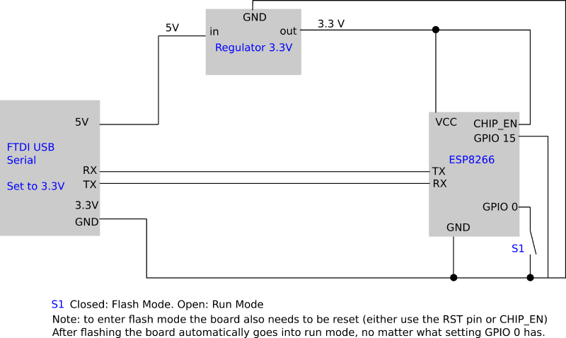
Use as a standalone Microcontroller Board
Installation Instructions for the Arduino IDE: https://github.com/esp8266/Arduino
Enter Flash mode (to upload new firmware):
and try to upload the example patch below:
/* ESP8266 as an Arduino
 *  Wiring:
 *  GPIO15 (IO15) to GND
 *  CHIP Enable to VCC (on some modules: CH_PD)
 *  GPIO0 (IO0) to GND
*/

void setup() {

  Serial.begin(115200);

}

void loop() {

  delay(1000);
  Serial.println("I'm there!!!!!");

}
pin mapping:
ESP8266 PINS
============
Arduino Pin 0 = IO0
Arduino Pin 1 = Blue LED
Arduino Pin 2 = IO2
Arduino Pin 3 = ??
Arduino Pin 4 = IO4
Arduino Pin 5 = IO5
Arduino Pin 6 = ??
Arduino Pin 7 = ??
Arduino Pin 8 = ??
Arduino Pin 12 = IO12
Arduino Pin 13 = IO13
Arduino Pin 14 = IO14
Arduino Pin 15 = IO15
UDP sending
#include <ESP8266WiFi.h>
#include <ESP8266mDNS.h>
#include <WiFiUdp.h>

WiFiUDP udp;
const char* ssid     = "yourWifiName";
const char* password = "yourPassword";
const char* hostString = "yourHostName";

void setup() {
  Serial.begin(57600);
  delay(100);
  Serial.println("\r\nsetup()");
  WiFi.hostname(hostString);
  WiFi.begin(ssid, password);
  while (WiFi.status() != WL_CONNECTED) {
    delay(250);
    Serial.print(".");
  }
  Serial.println("");
  Serial.print("Connected to ");
  Serial.println(ssid);
  Serial.print("IP address: ");
  Serial.println(WiFi.localIP());

 if (!MDNS.begin(hostString)) {
    Serial.println("Error setting up MDNS responder!");
 }
 Serial.println("mDNS responder started");

}

void loop() {

  IPAddress broadcastIp(192, 168, 0, 110);
  //IPAddress broadcastIp(255, 255, 255, 255);
  udp.beginPacket(broadcastIp,5555);
  udp.write("hi");
  udp.endPacket();
  delay(500);

}
Reverting Firmware to AT Firmware
This is for the esp-201 module, coming with 4mbit (512kB) flash.
Get the latest Firmware on the espressif bbs home page: http://bbs.espressif.com/viewtopic.php?f=46&t=2054 (this was last checked 2016-05-10 - there might be a more up to date version now)
either use the flash download tool from the above linked page or for example the very useful esptool: https://github.com/themadinventor/esptool
extract the downloaded files, open a shell and change into the directory "/ESP8266_NONOS_SDK/bin"
esptool.py --port /dev/ttyUSB0 write_flash 0x00000 boot_v1.2.bin 0x01000 at/512+512/user1.1024.new.2.bin 0x3e000 blank.bin 0x7e000 blank.binor for an original ai thinker firmware: download esp_iot_sdk_v0.9.5_15_01_23.zip
esptool.py --port /dev/ttyUSB1 write_flash 0x00000 boot_v1.2.bin 0x01000 at/user1.512.new.bin 0x3e000 blank.bin 0x7e000 blank.bin
