GMU:Tutorials/Performance Platform/Videowall Calibration: Difference between revisions
| (98 intermediate revisions by the same user not shown) | |||
| Line 1: | Line 1: | ||
== Introduction == | |||
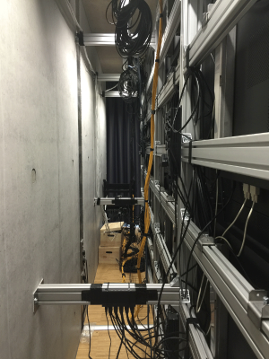
The video wall consists of 4*4 screens, which are connected with each other with serial ports. And all the signal will processed by the signal box which will provide a HDMI port to connect to the computer. The signal from the computer can be then distributed through the box to each screen. | |||
And the screens are actually connected in the order that the picture shows below. | |||
== | [[File:backofwall.png|thumb|left|Behind Video Wall|300px]] | ||
[[File:screenbox.png|thumb|left|Signal Box|300px]] | |||
[[File:grid.png|thumb|left|Numbers Of All Screens|300px]] | |||
<br style="clear:both"> | |||
Useful links: | |||
More info about the Screens: | |||
[http://www.eyevis.de/produkte/lcd-loesungen/videowand-lcd/eye-lcd-5500-xsn-ld-fx.html] | |||
Manual: | |||
[http://www.eyevis.de/files/um_eye-lcd-5500-xsn-ld-fx_en_v1.0_e03_1.pdf] | |||
<br style="clear:both"> | |||
== Part 1 With Remote Control == | == Part 1 With Remote Control == | ||
[[File: | |||
The infrared receiver is attached to the right side frame of the video wall. So the screen will react only when you target your remote control towards the infrared receiver. | |||
[[File:remotecontrolll.png|thumb|left|Remote Control|300px]] | |||
[[File:receive.png|thumb|left|Infrared Receiver|300px]] | |||
<br style="clear:both"> | |||
<br/> | |||
When you press the "menu" button on the remote control, you can activate the adjustment menu on the screen which is located on the lower right corner. That is actually no.1 screen. You can use the arrow buttons in the menu to do specific adjustments which will have an effect on all the screens. Detailed instructions can be found in the Manual PDF from page 41 to 51. | |||
[[File:picture.png|thumb|left|Picture|300px]] | |||
[[File:display.png|thumb|left|Display|300px]] | |||
[[File:ssetup.png|thumb|left|Setup|300px]] | |||
[[File:input.png|thumb|left|Input|300px]] | |||
<br style="clear:both"> | |||
In order to change some settings for individual screens, you need to press "select" button, so that you can see each screen will display some informations containing the number of its own. Then you can choose the screen you want to adjust by pressing the corresponding number on the remote control. In this way, you can make some changes individually. | |||
[[File:videowalll.png|thumb|left|Select|400px]] | |||
<br/> | |||
<br style="clear:both"> | |||
== Part 2 With Software == | == Part 2 With Software == | ||
The softwares will be used only work for Windows. They are uploaded to Google Drive.[https://drive.google.com/folderview?id=0BwFYVbmk3aHYUkUzS2cyWndQSlk&usp=sharing] | |||
The route for each program is listed below. | |||
'''1. NPort Windows Driver Manager''' | |||
Google Drive\EYEVIS-Color-Calibration\Moxa\Downloaded\drvmgr_setup_Ver1.18_Build_15022515_whql.exe | |||
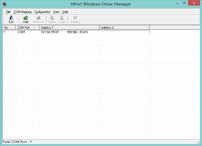
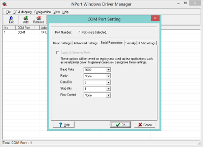
You have to install this program for configuring the proper port for screens in order to get the other two softwares working. After installation, you can get access to configure the COM port settings. | |||
Usually, we only need to change the numbers at "Serial Parameters", such as "Baud Rate". | |||
[[File:moxa0.png|thumb|left|400px]][[File:moxa1.png|thumb|left|400px]][[File:moxa2.png|thumb|left|400px]] | |||
Here is a video setting tutorial: [https://www.youtube.com/watch?v=1gNnMDqkCm0] | |||
<br style="clear:both"> | |||
'''2. eye Device Setup''' | |||
Google Drive\EYEVIS-Color-Calibration\eyeDeviceSetup\Software\eyeDeviceSetup.exe | |||
<br style="clear:both"> | |||
'''3. EYE-LCD-CAS''' | |||
Google Drive\EYEVIS-Color-Calibration\EYE-LCD-CAS\Software\eyeLCD-CAS.exe | |||
<br style="clear:both"> | |||
[[File:1-user.png|thumb|User|left|300px]] | |||
[[File:2-setup.png|thumb|Setup|left|300px]] | |||
[[File:3-service.png|thumb|Service|left|300px]] | |||
[[File:4-status.png|thumb|Status|left|300px]] | |||
[[File:5-gamma.png|thumb|Gamma|left|300px]] | |||
[[File:6-preference.png|thumb|Preference|left|300px]] | |||
[[File:7-reports.png|thumb|Reports|left|300px]] | |||
Latest revision as of 13:38, 28 July 2016
Introduction
The video wall consists of 4*4 screens, which are connected with each other with serial ports. And all the signal will processed by the signal box which will provide a HDMI port to connect to the computer. The signal from the computer can be then distributed through the box to each screen. And the screens are actually connected in the order that the picture shows below.
Useful links:
More info about the Screens: [1] Manual: [2]
Part 1 With Remote Control
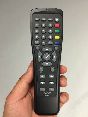
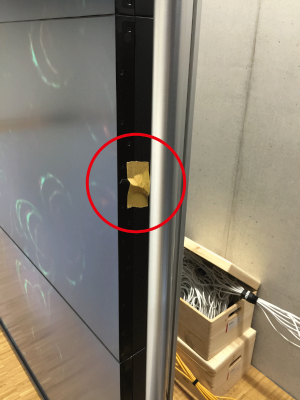
The infrared receiver is attached to the right side frame of the video wall. So the screen will react only when you target your remote control towards the infrared receiver.
When you press the "menu" button on the remote control, you can activate the adjustment menu on the screen which is located on the lower right corner. That is actually no.1 screen. You can use the arrow buttons in the menu to do specific adjustments which will have an effect on all the screens. Detailed instructions can be found in the Manual PDF from page 41 to 51.
In order to change some settings for individual screens, you need to press "select" button, so that you can see each screen will display some informations containing the number of its own. Then you can choose the screen you want to adjust by pressing the corresponding number on the remote control. In this way, you can make some changes individually.
Part 2 With Software
The softwares will be used only work for Windows. They are uploaded to Google Drive.[3]
The route for each program is listed below.
1. NPort Windows Driver Manager
Google Drive\EYEVIS-Color-Calibration\Moxa\Downloaded\drvmgr_setup_Ver1.18_Build_15022515_whql.exe
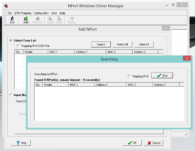
You have to install this program for configuring the proper port for screens in order to get the other two softwares working. After installation, you can get access to configure the COM port settings. Usually, we only need to change the numbers at "Serial Parameters", such as "Baud Rate".
Here is a video setting tutorial: [4]
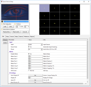
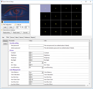
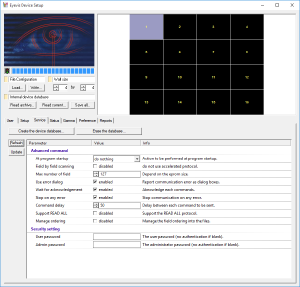
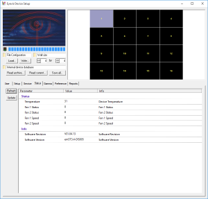
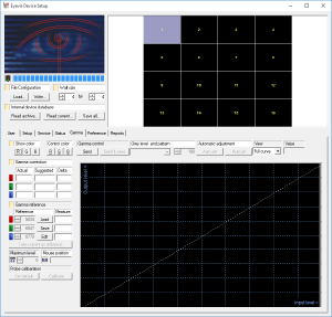
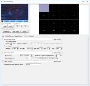
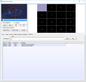
2. eye Device Setup
Google Drive\EYEVIS-Color-Calibration\eyeDeviceSetup\Software\eyeDeviceSetup.exe
3. EYE-LCD-CAS
Google Drive\EYEVIS-Color-Calibration\EYE-LCD-CAS\Software\eyeLCD-CAS.exe
