GMU:Designing Utopias: Theory and Practice/Selena Deger: Difference between revisions
No edit summary |
|||
| Line 3: | Line 3: | ||
https://wiki.keyestudio.com/KS0035_Microphone_Sound_Sensor_with_Potentiometer | https://wiki.keyestudio.com/KS0035_Microphone_Sound_Sensor_with_Potentiometer | ||
Analog sound sensor includes a microphone sensor to detect ambient sounds and loudness of them. In some sources usage is recommended with an audio analyzer module(https://www.dfrobot.com/product-514.html) to differentiate different frequencies. | Analog sound sensor includes a microphone sensor to detect ambient sounds and loudness of them. In some sources usage is recommended with an audio analyzer module(https://www.dfrobot.com/product-514.html) to differentiate different frequencies. | ||
https://www.sparkfun.com/products/15569 | https://www.sparkfun.com/products/15569 | ||
Ultrasound distance sensor consists of a trigger and receiver parts, one is releasing ultrasonic waves and the other is receiving the reflected waves to calculate the distance from the duration of the bouncing time. | |||
Ultrasound distance sensor consists of a trigger and receiver parts, one is releasing ultrasonic waves and the other is receiving the reflected waves to calculate the distance from the duration of the bouncing time. The detection range is 2-40cm. | |||
'''connecting to Arduino''' | '''connecting to Arduino''' | ||
| Line 13: | Line 16: | ||
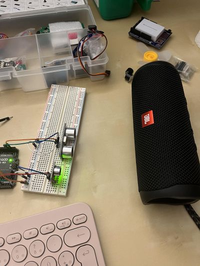
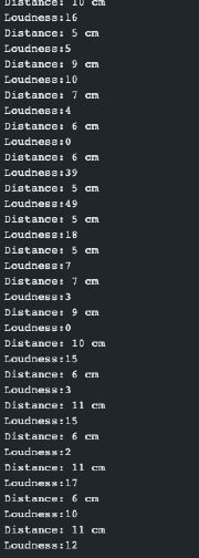
To see the differences in the values, I put some track on the bluetooth speaker and moved it in front of the distance sensor. | To see the differences in the values, I put some track on the bluetooth speaker and moved it in front of the distance sensor. | ||
[[File: sd_jbl. | |||
[[File:sd_jbl.jpg|400px]] | |||
[[File:sel_loud.png|180px]] | |||
'''creating the loop''' | |||
I have added a piezzo buzzer (+ 1K resistor) to the circuit to make the process of loudness detection more cyclical. I have followed this tutorial connecting it > https://surtrtech.com/2018/01/29/how-to-use-a-buzzer-piezo-speaker-with-arduino/ | |||
[[File:sd_buzzer.jpg|400px]] | |||
added the code a condition about the distance. When the distance is smaller than 10cm, buzzer starts to buzz with the mapped values also from the sound and distance sensor. | |||
Revision as of 22:00, 7 December 2022
07.12.22
Analog sound sensor and ultrasonic distance sensor
https://wiki.keyestudio.com/KS0035_Microphone_Sound_Sensor_with_Potentiometer
Analog sound sensor includes a microphone sensor to detect ambient sounds and loudness of them. In some sources usage is recommended with an audio analyzer module(https://www.dfrobot.com/product-514.html) to differentiate different frequencies.
https://www.sparkfun.com/products/15569
Ultrasound distance sensor consists of a trigger and receiver parts, one is releasing ultrasonic waves and the other is receiving the reflected waves to calculate the distance from the duration of the bouncing time. The detection range is 2-40cm.
connecting to Arduino
Analogue sound is connected to the analog pin, while trigger and receiver pins of the ultrasound sensor are connected to two different digital pins.
To see the differences in the values, I put some track on the bluetooth speaker and moved it in front of the distance sensor.
creating the loop
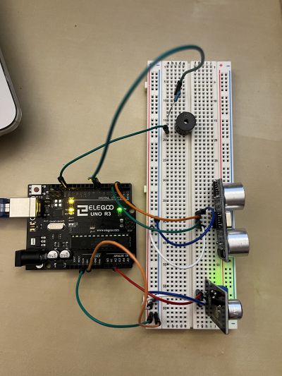
I have added a piezzo buzzer (+ 1K resistor) to the circuit to make the process of loudness detection more cyclical. I have followed this tutorial connecting it > https://surtrtech.com/2018/01/29/how-to-use-a-buzzer-piezo-speaker-with-arduino/
added the code a condition about the distance. When the distance is smaller than 10cm, buzzer starts to buzz with the mapped values also from the sound and distance sensor.
01.12.22
line tracking sensor
https://wiki.keyestudio.com/Ks0050_keyestudio_Line_Tracking_Sensor
Line tracking sensor is used for differentiating between black and white(either can be the backgorund/foreground) with the integrated infrared sensors(one emitting, one collecting). It is very dependent on the reflectiveness of the material/object therefore it is important to have a consistent and equal light source on the surface.
connecting to arduino
After following the instructions in the producer website, I have managed to get the first digital outputs from the sensor.
To get different numbers from the sensor(other than hi/lo), I connected it to an analog input.
void setup()
{
  Serial.begin(9600);
}
void loop()
{


  Serial.println(analogRead(A0)); // print the data from the sensor


  delay(500);
}
moving data to processing
Following this tutorial > https://www.arduino.cc/education/visualization-with-arduino-and-processing I have first uploaded this code snippet to the arduino
unsigned int ADCValue;
void setup(){
    Serial.begin(9600);
}

void loop(){

 int val = analogRead(0);
   val = map(val, 0, 300, 0, 255);
    Serial.println(val);
delay(50);
}
Lastly running different examples from the same tutorial on processing, resulted in different visualization of the black/white data retrieved from the sensor.


