No edit summary |
No edit summary |
||
| Line 2: | Line 2: | ||
[[File:pinballswich1.jpg]] | [[File:pinballswich1.jpg]] | ||
Ayla and me decided to make "simple pinball switches" in a box | Ayla and me decided to make "simple pinball switches" in a box | ||
| Line 10: | Line 11: | ||
help of some alligator clips we connected every obstacle on the inner side with | help of some alligator clips we connected every obstacle on the inner side with | ||
some copper wire to the breadboards. | some copper wire to the breadboards. | ||
[[File:pinballswich7.jpg]] | [[File:pinballswich7.jpg]] | ||
So each obstacle was one part of the switch. The circuit was closed when the ball | So each obstacle was one part of the switch. The circuit was closed when the ball | ||
that was wrapped in aluminium foil touched the positive and the negative part of | that was wrapped in aluminium foil touched the positive and the negative part of | ||
the obstacle. | the obstacle. | ||
[[File:pinballswich8.jpg]] | [[File:pinballswich8.jpg]] | ||
Because the speakers were inside the box, the sounds were a bit silent so we made | Because the speakers were inside the box, the sounds were a bit silent so we made | ||
some holes on the sides of the box and also some smaller ones on the board itself. | some holes on the sides of the box and also some smaller ones on the board itself. | ||
[[File:pinballswich3.jpg]] | [[File:pinballswich3.jpg]] | ||
While building we realized that it's always that you have to think about how to attach something to another part, make it stiff or make it flexible, also. | While building we realized that it's always that you have to think about how to attach something to another part, make it stiff or make it flexible, also. | ||
Inside the machine, we worked with five 555 timers in two different breadboards. | Inside the machine, we worked with five 555 timers in two different breadboards. | ||
The main constructions was the same but the values were varying in relation to different values of the resistors between the pins 6-7 and 7-8 and the capacitors between pins 1-2 and 3. | The main constructions was the same but the values were varying in relation to different values of the resistors between the pins 6-7 and 7-8 and the capacitors between pins 1-2 and 3. | ||
[[File: | |||
[[File:pinballswich4.jpg]] | |||
Circuits: | Circuits: | ||
1 ) R2 : 1 M ohm 2) R2: 10K ohm 3) R2: 100K ohm | 1 ) R2 : 1 M ohm 2) R2: 10K ohm 3) R2: 100K ohm | ||
| Line 33: | Line 41: | ||
1 - 2 : 0.1μF 1 - 2 : 0.1μF | 1 - 2 : 0.1μF 1 - 2 : 0.1μF | ||
3: 22 μF 3: 47μF | 3: 22 μF 3: 47μF | ||
[[File: | |||
[[File:pinballswich5.jpg]] | |||
Revision as of 20:29, 18 December 2015
Assignment I - „Improbable Switch“
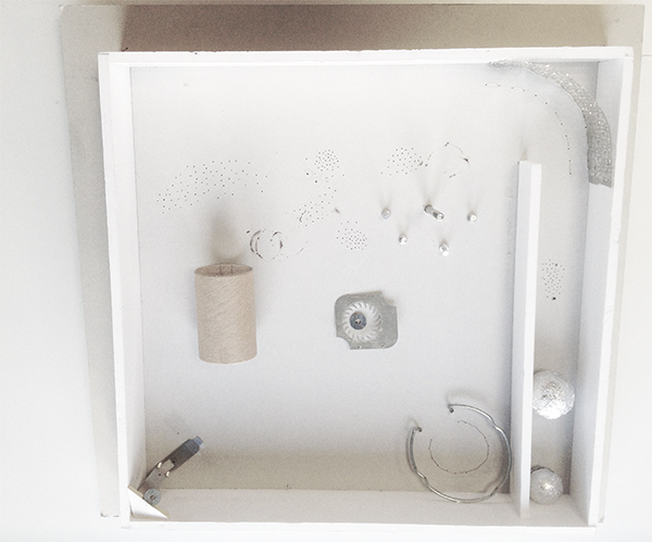
Ayla and me decided to make "simple pinball switches" in a box
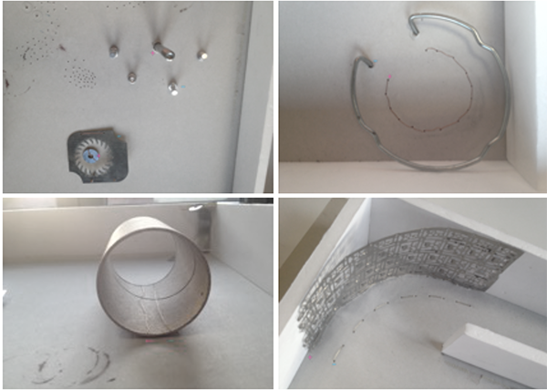
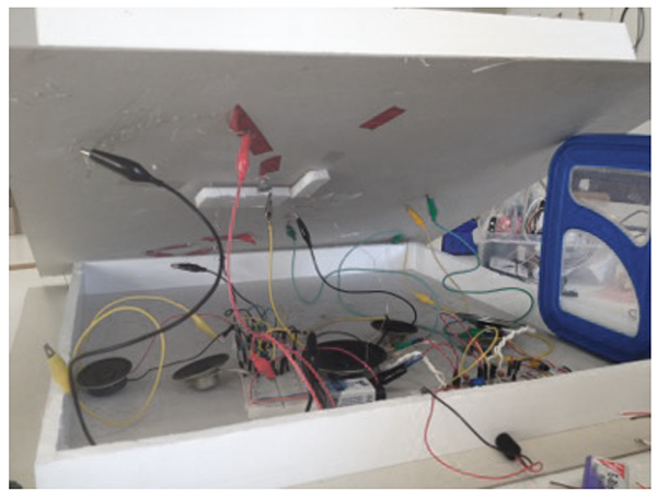
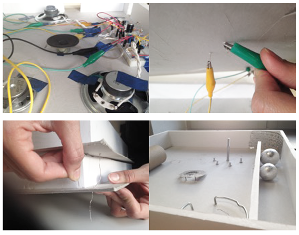
We went through some trash bins on the campus and found some thicker cardboard boxes, probably used by architecture students. We also found some conductive materials that were our six obstacles aka our six switches. Between the two cardboard boxes we put two breadboards that were creating five sounds. With the help of some alligator clips we connected every obstacle on the inner side with some copper wire to the breadboards.
So each obstacle was one part of the switch. The circuit was closed when the ball that was wrapped in aluminium foil touched the positive and the negative part of the obstacle.
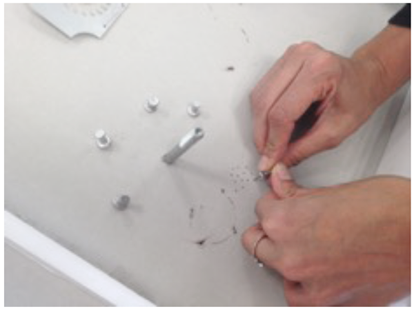
Because the speakers were inside the box, the sounds were a bit silent so we made some holes on the sides of the box and also some smaller ones on the board itself.
While building we realized that it's always that you have to think about how to attach something to another part, make it stiff or make it flexible, also.
Inside the machine, we worked with five 555 timers in two different breadboards.
The main constructions was the same but the values were varying in relation to different values of the resistors between the pins 6-7 and 7-8 and the capacitors between pins 1-2 and 3.
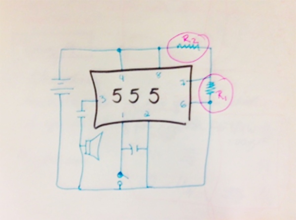 Circuits:
1 ) R2 : 1 M ohm 2) R2: 10K ohm 3) R2: 100K ohm
R1 : 100 K ohm R1: 10K ohm R1: 10K ohm
1 - 2 :0.1 μF 1 - 2 : 0.1 μF 1 - 2 : 0.1 μF
3: 1μF 3: 47μF 3: 100μF
4) R2 : 1K ohm 5) R2 : 10 K ohm
R1 : 1 K ohm R1 : 100 K ohm
1 - 2 : 0.1μF 1 - 2 : 0.1μF
3: 22 μF 3: 47μF
