No edit summary |
No edit summary |
||
| Line 7: | Line 7: | ||
Note that the transistor "2N5457" we are using this semester has a slighlty different pinout. Therefore the connections are slighlty different as shown in the photos below. We also need a resistor for draining spurious voltages on the piezo to ground. Without this resistor the amplifier could drift into clipping, outputting no sound at all. The smaller the resistor the lower the gain of the amplifier. Try with a 100kOhm resistor first (yellow band). | Note that the transistor "2N5457" we are using this semester has a slighlty different pinout. Therefore the connections are slighlty different as shown in the photos below. We also need a resistor for draining spurious voltages on the piezo to ground. Without this resistor the amplifier could drift into clipping, outputting no sound at all. The smaller the resistor the lower the gain of the amplifier. Try with a 100kOhm resistor first (yellow band). | ||
[[File:piezo_connections.png|800px| | [[File:piezo_connections.png|800px|thumb|piezo preamp solder connections]] | ||
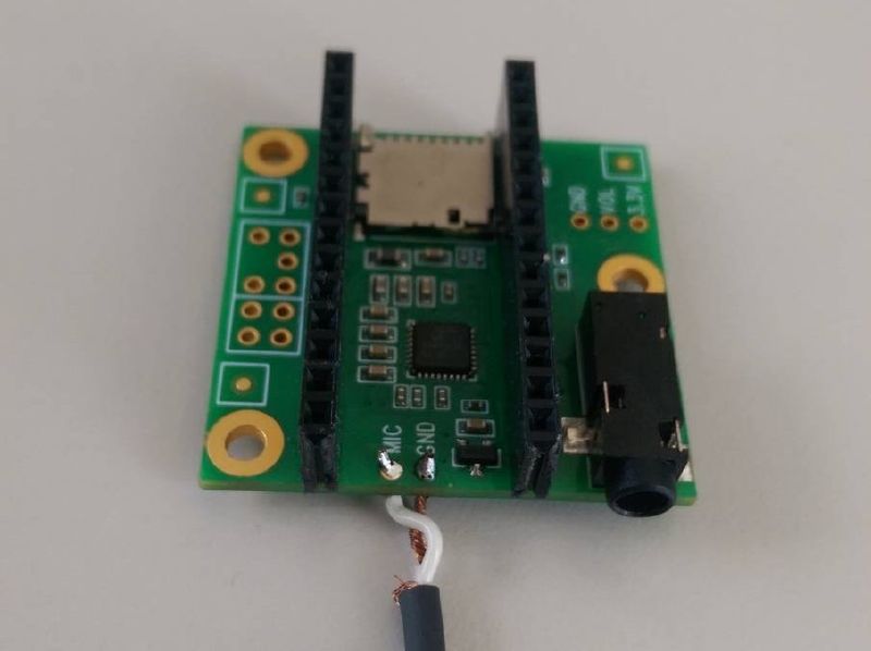
[[File:teensy_connections.jpeg|800px|teensy microphone input soldering]] | [[File:teensy_connections.jpeg|800px|teensy microphone input soldering]] | ||
Revision as of 15:51, 25 May 2021
I made two videos showing how to solder the teensy headers and the piezo amplifier and cable.
Note that the transistor "2N5457" we are using this semester has a slighlty different pinout. Therefore the connections are slighlty different as shown in the photos below. We also need a resistor for draining spurious voltages on the piezo to ground. Without this resistor the amplifier could drift into clipping, outputting no sound at all. The smaller the resistor the lower the gain of the amplifier. Try with a 100kOhm resistor first (yellow band).

