Semesterproject
"Police Car Badge"
Idea:
The first time I came into contact with the topic of PCB Art was through this module. Before I knew what PCBs were and how they are typically used but I didn’t know about the large community that uses this medium in an artistical way. What really fascinated me is the big part of this community that is just dedicated on making PCBs into badges. So for my final project I created such a badge.
The whole design of the PCB is based on the functionality of the first schematic I searched out to practice in KiCad with. Over my development time on this project, the schematic and with it the circuit, as well as the design have gone through a few changes and adjustments.
The basic board design is made to look like an old school american police car. The main function of the circuit I used, is to flash two LEDs alternately. This reminded me of a siren typically mounted on top of police cars, ambulances or firefighting vehicles. This inspired me to design a PCB with the design of an old police car. To make the board a bit more interesting I added more LEDs, so not only the sirens would flash but also the headlights of the car would light up.
Schematic and Circuit:
The circuit of my board can be separated into three different sections.
The power supply that consists of a nine-volt battery, that provides the entire circuit with power and a switch with which you can join and break the powerline connection to the rest of the circuit, so the LEDs turn on and off.
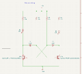
The second section is a circuit for blinking two LEDs using transistors. This type of circuit is called an "Astable Multivibrator Circuit". The voltage on the left side of the capacitor "C2" controls the transistor "Q1B" and voltage on the right side of the capacitor "C1" controls the transistor "Q1A". When the power source of the circuit is turned on it charges the two capacitors "C1" and "C2". They will alternate between being charged and discharged and by doing this they turn the transistors on and off. When "Q1B" turns on, it changes the voltage of "C1" so that "Q1A" turns off. By turning on "Q1B" it allows current to flow through it so that the LED "D1" lights up. It stops being lit when "Q1B" is turned off. After a short while, the voltage of "C1" rises up again and turns on the transistor "Q1A". When transistor "Q1A" turns on, it changes the voltage of "C2" so that "Q1B" turns off. By turning on "Q1A" it allows current to flow through it so that the LED "D2" lights up. It also stops being lit when "Q1A" is turned off. This keeps repeating as long as the power source is connected to the circuit. The resistors "R2" and "R3" have the function to slow down the charging process of the two capacitors, so that the transistors only turn on and off at a moderate rate and the LEDs blink alternately instead of lighting up constantly. The Resistors "R1" and "R4" are only there to set the current through the LEDs.
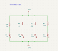
The third section is much simpler than the second. It only consists of four LEDs and four resistors. Above each LED a resistor is connected to it. The resistors regulate the voltage that flows into the LEDs. If these LEDs are submitted to much current they will burn out.
Here is the link to the website that I used as research. It explains the "Astable Multivibrator Circuit", from which I build up my schematic and circuit from:
https://www.build-electronic-circuits.com/astable-multivibrator/
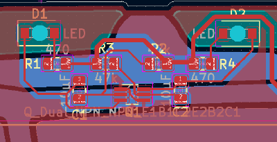
The circuit on the actual PCB board is a bit different. Instead of two transistors with each three pins, there is only one transistor with six pins. Both transistors are in one chip but it still fulfils all the functions of the two transistors. It just simplifies the circuit and saves some space.
Design:
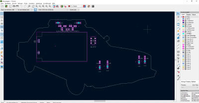
Like I have written in the first part of my documentation I've designed my PCB board to look like an american old school police car. I was generally inspired by the functionality of the "Astable Multivibrator Circuit". The two alternately blinking LEDs of the circuit reminded me of the typical police sirens. I chose this look of an old school police car because it is such an iconic design that everybody can recognize. I searched out some reference pictures and designed a drawing of the car in Inkscape. The model of the car I used as reference primarily is black and white but because I wanted to bring more color into the design, I changed the body of the car to be silver as well as changed the car doors and the engine hood to be green. This color scheme is more or less reminiscent of older german police cars.
When I was satisfied with my design, I imported the finished layout into KiCad and aligned all the different layers. The actual police car design is placed on the backside of the PCB, whereas the circuit with all its parts, is located on the frontside. After aligning the design, I placed the components on the frontside of the board in an optimal way. Starting with where I needed the LEDs to be and then went from there. After placing all the components, I drew in the circuit tracks to connect all of parts in the same manner visualized in the schematics.
The frontside is covered with copper. This copper layer fulfills the role of the GND circuit tracks, which connects the rest of the circuit with the power supply. Of course there still are the general circuit tracks, that connect everything together, so power can reach all the components and the circuit can function. Furthermore, there are labels corresponding to each component. When soldering the parts to the board, it is much easier because you know where to exactly place them. There also is a placeholder label for the manufacturer, that is covered up by the battery holder. In the production of the board the label was exchanged with a manufacturing number. Lastly, I put a short warning on the PCB, as a homage to one of my friends. All these labels are placed on the frontside Silkscreen layer.
Before I explain the backside of my board, I wanted to comment on the components I used for my PCB. Almost all of the parts are SMD components, that have to be mounted only on one side on the board, facing outward. In the case of my project, it is the frontside. The battery holders on the other hand need through holes drilled into the board and copper pads on the backside of the board, so they can be soldered to it. The LEDs I used also need through holes because they are a special type of LEDs, called reverse mount LEDs. They are mounted on the board facing inward. The middle part of the LED is placed into the hole, while the pads of the LEDs still sit on the frontside of the board. With this way they shine through the PCB. I designed it like that because I wanted the side of the PCB board with the actual design to look neat and flat but I also wanted the parts of the layout resembling the siren and headlight to light up/blink.
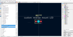
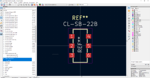
I altered the footprint for a reverse mounted LED, that already exists in the KiCad footprint library, a bit to better fit the LED I wanted to buy and solder to my PCB. To do that I used the data sheet for the component, that I got from the manufacturer’s website. I repeated the same process for the slider switches footprint but instead of changing an already existing one I made it on my own by recreating the recommended layout found in the parts data sheet.
Components:
- 1x 9 Volt Battery holder
- 1x SMD Slider Switch
- 8x SMD Resistors (4x 100Ω/2x 500Ω/2x 47kΩ)
- 2x SMD Capacitors (10μF)
- 1x SMD Transistor
- 4x SMD reverse mount LEDs white
- 1x SMD reverse mount LED blue
- 1x SMD reverse mount LED red
Now let‘s get to the backside layout. Whit the method of stacking different layers on top of each other you can achieve a wider range of colors and materials, than just the layers on their own. This is exactly what I did. Normally when you assign a layer just to be copper it will always have a soldermask layer above it. To give the body of the police car that silver color I stacked the soldermask and copper layer on top of each other, to expose the metal. For the wheels, the windows, the siren holder and the radiator cowling at the front of the car I just assigned them to be one layer of copper. The soldermask layered above the copper is a bit lighter in color and because the copper layer is about 35µm thick you can see and feel a height difference between the different layers. The windshield has some reflection highlights on it. To do this I created a silkscreen layer above the copper layer of the window. For the sirenlights and the headlights of the police car I made the layer to just be soldermask. This exposes the bare PCB Material. In this case it is FR-4, glass fiber. FR-4 lets the light of the LEDs shine through it, not just through the holes. I also assigned the parts of the design that are made to look like the car doors and engine hood a soldermask layer. With this you can see the bare PCB as well.
When I was happy with my layout and design of the PCB in KiCad I finally ordered it from JLCPCB. I changed the material of the copper layers to HASL, so the car body is actually silver, not copper. I changed the color of the soldermask layer to black and the silkscreen was already set to white, the color I wanted.
After a while I finally received the PCBs and they look nice. I am just a bit disappointed by the streakiness of the silkscreen layer.
Finished project:
The PCB board is about 83mm times 153mm and it is 1,6mm thick.
Before actually finishing the board, I had to get new capacitors because the ones I bought before did not have the right capacity.
I had to improvise a bit and the end result looks clunky, since the capacitors a quite big. They lie above and overlap with the resistors R1 and R4 but because of the plastic at the bottom of the parts they do not interfere with the resistors.
I had some spare resistors left and I experimented with them. I soldered two on top of the resistors R2 and R3, that were already mounted on the board, so that they are connected in parallel to each other. By doing this I increased the blinking speed of the LEDs.
It functions how I wanted it to and I am happy with that.
When I was finished with the soldering process, I clipped of the pin from the battery holder that was sticking out from the backside of the PCB. But only the top one. The one pin below that I bend to make it look like a door handle. As a last step I cut out green, orange, red and blue crafting foil in the shape of the sirenlights, the headlights, the car doors and the hood of the car. I stuck the foil onto the board and with this my badge is finally complete. Now it has all the colors I wanted it to have but I could not create, due to the limited option of layers and colors.
GitHub Repository: https://github.com/Rik3Kat/PoliceCar_PCBArts
With my GitHub repository you have access to the KiCad files for my project, I developed over the span of this course and download them.
Here are two videos demonstrating the functionality of my PCB:
Here are the links to some of the projects I showed you and a short documentary about the DEFCON 2018:


