DEVICES OF PERCEPTION
BASICS
ASSIGNMENTS
ASSIGNEMENT N° 1 - LOUDNESS KILL SWITCH
MONOSTABLE 555 - MOMENTARY SWITCH
The first assignment was to build a "super conceptual switch" of any sort.
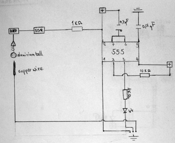
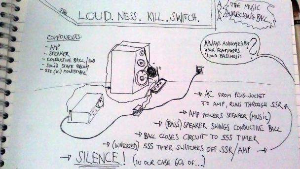
The "Loudness Kill Switch" reacts to the loudness of music emitted from a speaker. If the music reaches a certain volume it will switch its self off for a set period of time.
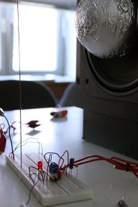
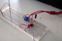
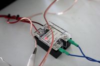
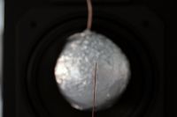
The mechanical construction consists of an aluminum foil wrapped ball hanging freely on a cable in front of a loudspeaker. Positioned in front of the speaker there is a copper rod. The bass reflex of the music lets the ball swing towards the copper rod and therefore eventually closes the circuit. The circuit consists of a "555 Timer" in Monostable Mode with it's high and low being inverted. With the ball and rod acting as a momentary switch triggering the 555 timer. The 555 timer controls a solid state relay, which powers the amplifier serving as a music output to the speaker. The sensitivity of this conceptual switch can be adjusted by simply moving the copper rod closer or further from the speaker. The time the music shall stay mute can be adjusted through the resistor used on the 555 timer (we usually had it set to 30 sec.).
This contraption can be on one hand viewed as a practical device, which in some form could come in handy for living with noisy flatmates... for us the circuit its self is the interesting part. Converting electric power to mechanical, and in the end the system feedbacking on itself, or rather limiting itself as soon as life starts being fun
Parts:
Styrofoam ball wrapped with aluminium foil |
Copper rod |
555 Timer |
Solid State Relay |
Loudspeaker |
Amplifier |
<videoflash type=vimeo>101017288|610|340</videoflash>
ASSIGNEMENT N° 2 - VEHICLE, MODEL N° 1
ASTABLE 555 - PHOTODIODE as a SWITCH
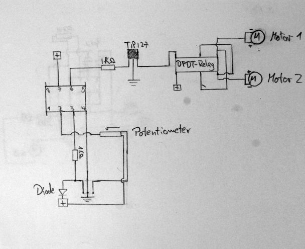
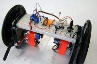
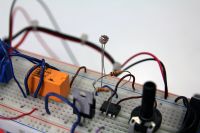
After having learnt about the IC 741 aka the comparator circuit, it was our goal to utilize this in our second assignment. The other parts we were able to scavenge across the classroom. Two motors attached to the breadboard transformed our circuit into a little vehicle. The comparator circuit was controlled through a photo resistor. Depending on the amount of light hitting the photo resistor the state would be either high or low. A relay set up as an H-Bridge would transfer high and low two forward or backward movement of the motors. Originally we wanted to mirror this circuit on the breadboard so both motors could be controlled independently. Unfortunately we were missing a second Transistor (TIP-127) to be able to finalize our plans that weekend. Although not being able to complete our second assignment to the extend we had originally imagined, we somehow had the feeling our vehicle was developing it's own character in a way. e.g. it could be programmed to be shy of the dark, and stop driving when it leaves a well lit space. The jerkyness it had when changing directions, or it staying upright through it's low center of gravity somehow added to this impression.
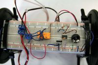
COMPONENTS:
1x
Double Pole Double Throw - Relay |
TIP 127 |
741 Comparator |
Photodiode |
2x
Battery |
<videoflash type=vimeo>101016951|610|340</videoflash>
ASSIGNEMENT N° 3 - DRAWING MACHINE
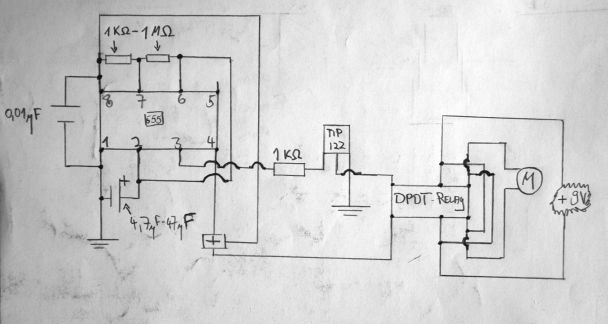
We used the same circuit twice to run the two motors
ASTABLE 555 - RESISTORS as SWITCHES
VEHICLE, MODEL N° 2, DRAWING MACHINE
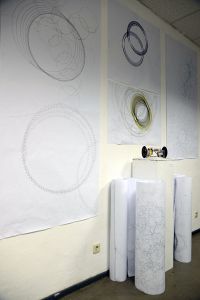
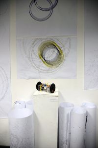
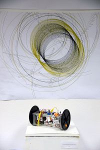
The basis for our third assignment was the previous one. Instead of the photodiode's resistance triggering the Double Pole Double Throw - Relay, we decided to only work with the common resistors and capacitors as our aim was to make the vehicle move in a certain rhythm. We added another Double Pole Double Throw - Relay, two 555 Timers and two TIP 122 to the breadboard. This allowed us to control both of the motors separately from each other.
To improve: Add photodiodes so that you can influence the rhythm of the motors moving forwards/backwards permanently.
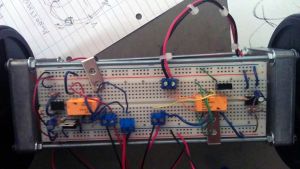
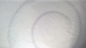
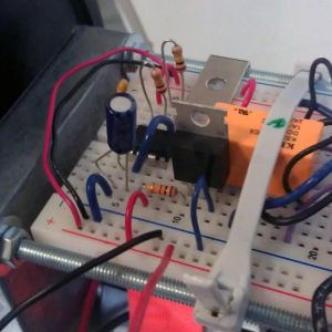
Parts: 2x Double Pole Double Throw - Relay | TIP 122 |
555 Timer |
3x Battery |
SUMMAERY - PRESENTATION
<videoflash type=vimeo>101011710|610|340</videoflash>
