How can we tell a machine how to react to different situations and stimuli ?
Introduction
The state machine is an important concept in theoretical Computer Science.
The following article explains how this concept can be used to program and organize different actions of simple robots.
Apparently there are:
- different reactions (outputs)
—> a robot can for instance move forward and backward, it can turn right or left and it can stand still.
- different stimuli (inputs)
—> a robot can for instance sense an obstacle (a wall), a human, …
- different situations (states)
—> a robot can for instance be looking for a power plug, it can be running away from an opponent or it can be in resting mode.
We can imagine that only one possible output (action) is not enough to react to a diversity of inputs (stimuli) -
It might be a good idea to move towards the closest wall if we are looking for a power plug. At the same time this would be rather bad if we are being chased by a prosecutor.
We can also imagine that a suitable program can easily get quite complex and messy.
Furthermore there is a good chance that some important relations between situations and reactions get lost in the programming process.
So how can we make the whole thing a bit clearer?
Structure
A good way to deal with the possible complexity of such a program is to draw a corresponding diagram.
There is another useful concept in theoretical Computer Science that can help us doing that:
It says that it is enough to conduct only one predefined action (output) in reaction to the current situation (state) and to then look at the input data in order to analyze and decide the next situation (and so forth..).
This kind of action pattern (Moore Machine) can be used in order to disassemble, restructure and consequently simplify similar sequences of much higher complexity (Mealy Machine).
And how can we use this strategy for our diagram?
We simply need to write down and structure the following things:
- every possible situation (state)
—> hungry, looking for food, eating, ..
- the particular conditions in which the situation (state) is changed
—> if sleeping and getting hungry -> looking for food, if looking for food and food has been found -> eating, ..
- a list that includes every situation (state) in connection to one specific action (output) that is carried out as soon as the corresponding state arrives —> looking for food / move around, eating / stop, ..
Example: developing the control mechanism of an autonomous vacuum cleaner
All of the above will become much clearer if we look at an practical example of an autonomous vacuum cleaner robot.
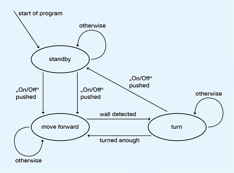
Step by step we will think of everything the robot has to do, put it in the right order and draw an appropriate diagram.
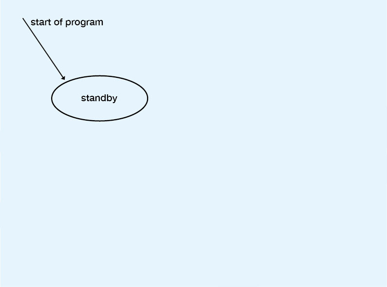
1) Turned on
The robot stands still and waits for further instructions.
It is now in standby mode.
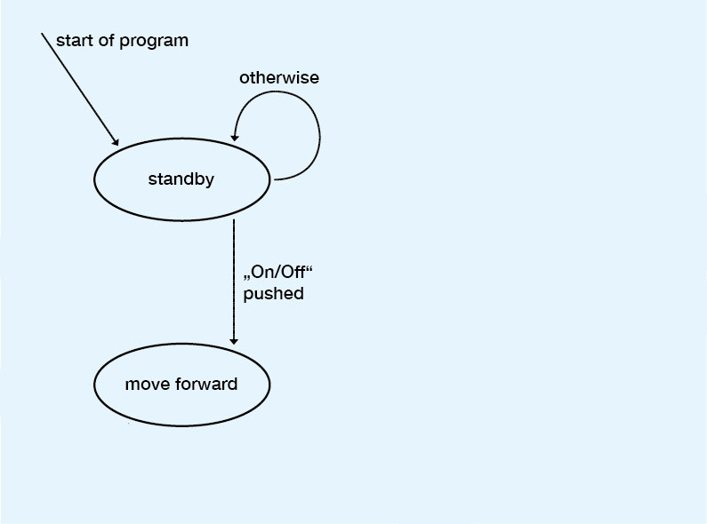
2) On / Off - button pushed
The robot starts to clean the room.
It moves forward and activates the air pump.
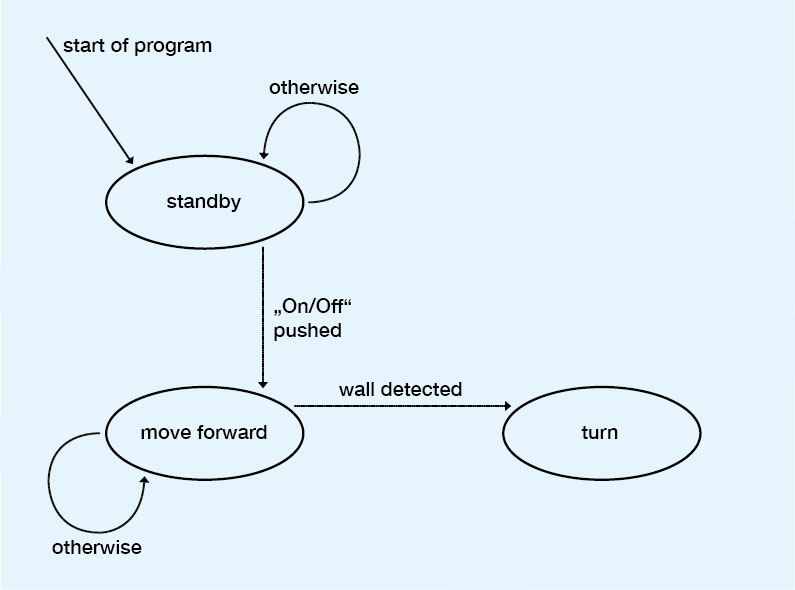
3) Approaching a wall
The robot would bump into the next wall if it would only be able to move forward.
It therefore needs a function that recognizes walls and makes the robot turn around.
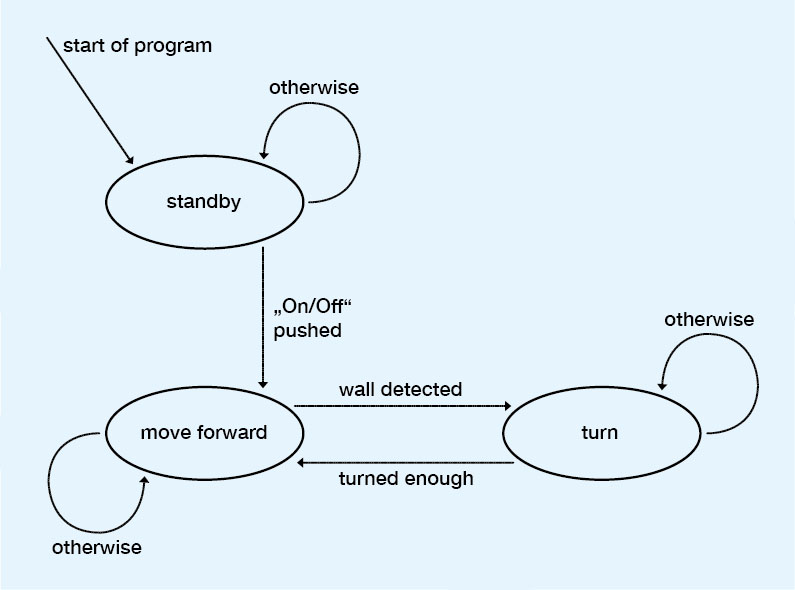
4) Turning around
So far the robot turns randomly in any direction.
We have to define a parameter that tells the robot if it turned enough in order to continue cleaning.
This parameter can be a time delay, a certain amount of wheel revolutions or the value of a (distance, ..) sensor.
5) Turned off
The final missing part is the off-button.
Writing the Program
Translating our diagram into a functional program is a relatively simple task.
Step 1: saving the current state into a variable
First of all we need a variable that saves the current state. It represents our State Machines memory.
The most suitable type for such a variable is in this case an „enum“.
This enum assigns different names to values:
Note (enum + Processing): the definition of an enum has to be saved in a separate file (tab) with an .java extension.
(more info )
Step 2: choosing alternative actions
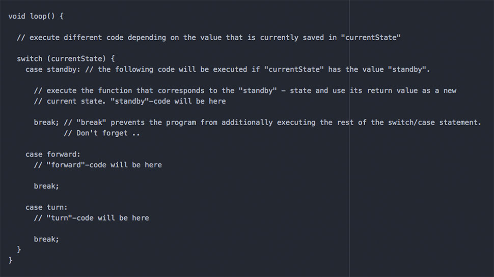
Now we need something that executes different code depending on the current state.
For this purpose we will have a closer look at the switch/case statement.
It operates similar to an if-condition whereas it can choose from more than two (if… else..) alternatives.
It could for instance run over and over again in the main loop-function of our program:
Step 3: defining the practical behavior of each state
From now on it makes sense to use functions (aggregation of code) in order to keep a clean overview of our program.
Each function includes the particular code that defines the behavior of a certain state.
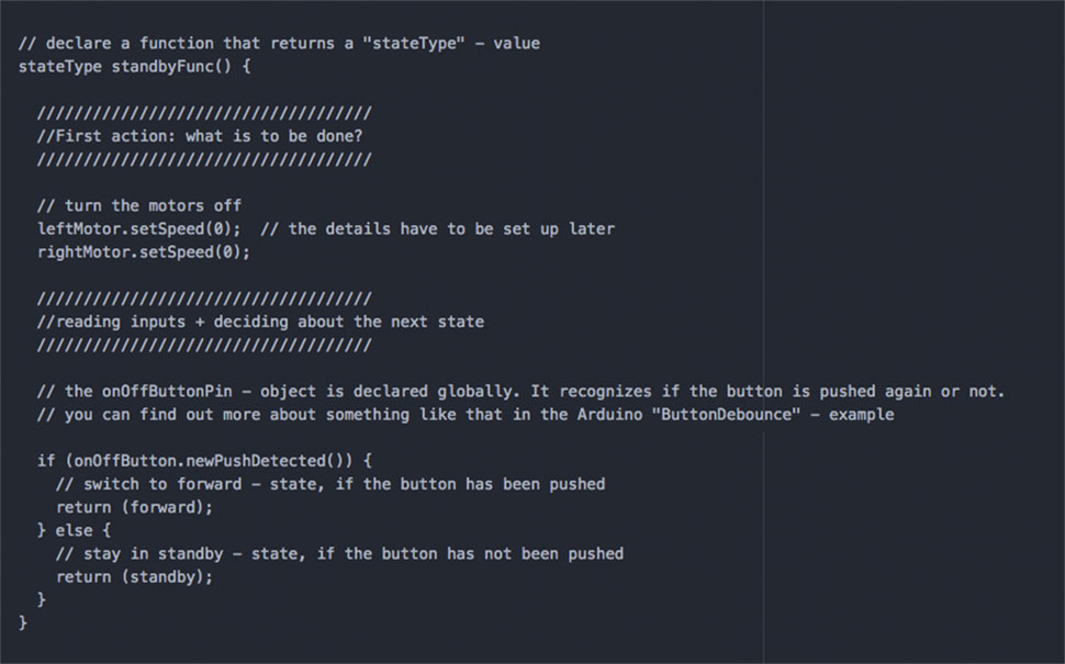
The internal structure of these functions is always the same:
1) conduct actions that fit to the particular state. (turn motors on / off, start a timer, ..) 2) read input data (sensors, timer, ..) that provides information about the next possible state 3) decide the next state
The third part can be done quite comfortably by giving back the new „state“ - value in form of the functions „return“ - value into the main loop.
This is an example of how the „standy“-state could look like:
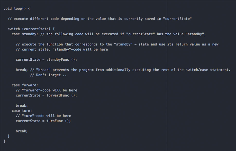
Step 4: assembling everything
We can now call each particular function in the appropriate part of the switch/case statement.
The functions return value is saved in the state variable for the next loop.
Step 5: extending the program
This kind of program structure can easily be extended by additional states without disturbing the overall clarity.
Therefore it makes sense to begin with a simple structure and to then add functions that are more complex.
