Tutorial: Working with Bluetooth

We are currently trying to establisch a connection between our PC and our Arduino. For this we are trying to use a bluetooth transiever, the HC 05. In our first attempt, we useing the HC 05 as a receiver, which reads input data from our computer.

Hardware:

  • Arduino Uno R3
  • HC 05 Bluetooth
  • Bluetooth capable PC

First things first, we need to setup our devises.  Here the resistors are 100 Ohm each. This is due to the TX/RX needing 3.3V. Also keep in mind, that the RX goes to TX and vice versa.

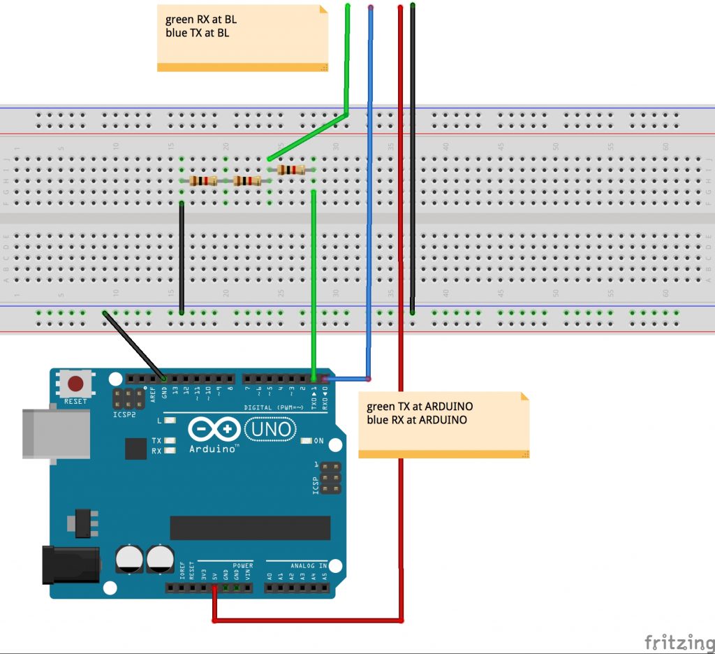
Once we’ve got the setup, its time for the software. Herefor we are useing Processing on  PC (Win 10) to send and the Arduino IDE for the recieving arduino. Later on we are going to do it the other way around.

Step two would be pairing with the bluetooth device we just hooked up to the arduino. Under Win10 you can achieve it like follows:

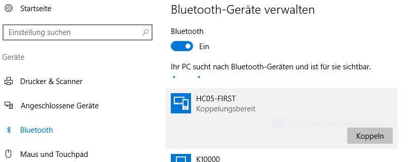
  • Step 1: Open your „Options“ pannel and search for „Bluetooth“.  Once done, you will get a list of all available devices in your current area. Select the device you are trying to pair with and press „Pair“.

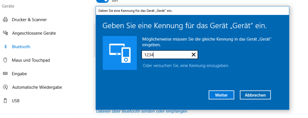
  • Step 2: Now the pannel will ask you for a password. If defaul it should be „1234“, if this does not work, you can look up/change the password. (For this you have to enter the AT Command Mode of the device. One can do this as discribed in this post:   AT Command Mode )

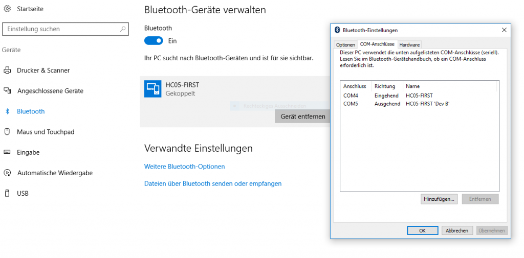
  • Step 3: Now that you have paired, all you need to know is on which port. For this click on „Extended Options“. it should list the serial ports of your PC. In our case the „COM5“, because it is outgoing.

Now we have a finnished setup and its time for some code. Since our first objektiv is sending data to our arduino, it needs to be able to recieve it. For this code to work move the TX pin to pin 8 and the RX pin to pin 7!

#include <SoftwareSerial.h>
SoftwareSerial mySerial(7, 8);

void setup() {
  Serial.begin(9600);
  mySerial.begin(9600);
}

void loop() {
  char to_read;
  
  //while there is a signal from our HC 5
  //print it!
  while (mySerial.available()) {
    to_read = mySerial.read();
    Serial.print(to_read);
  }
}

In the code above, the arduino recieves data via the Serialports und prints it. The counter part would be the PC sending data via Processing. This looks as follows:

import processing.serial.*; 
 
//Serial port object: 
Serial arduino;       
final int  baudRate   = 9600; 
final char delimiter = '\n'; 
 
void setup() { 
  //list all the available serial ports: 
  println("Available Serial Ports:"); 
 
  //Choose your Bluetooth port:
  printArray(Serial.list()); 

  //and enter its position here:        🢃                  
  final String portName = Serial.list()[2]; 
  println("\nOpening Serial Port: " + portName);
  
  //Create instance:  
  arduino = new Serial(this, portName, baudRate); 
 
  size(500, 500); 
  textSize(16); 
} 
 
void draw() { 
  background(0);  //window: black 
  text(str(mousePressed), mouseX, mouseY); 
 
  if (mousePressed) { 
   arduino.write('a');  
  } 
}

This code was provided by Johannes Deich. What it does is open a window which tracks your current mouse position and when you left-click it writes ‚a‘ to the serialport.

All done, we have now established the connection and are sending information from PC to Arduino!

Now its time for the other direction, PC recieves data sent by the Arduino. The setup is exactly the same, only that now we have an incomming port, „COM4“ (See picture „Step 3“). Connect PC to bluetooth device as shown above and keep the current Bluetooth circuit. Again we are going to work with the Arduino IDE and Processing, since it would be nice being capable to merge both communication ways, since the only diffrence is the sofware code aspect. Here the arduino code looks as follows:

//We are only going to print on 
//our Serialport, nothing else

void setup() {
  Serial.begin(9600);
}

void loop() {
  for(int i=0; i<9; i++){
    Serial.print("data ");
    Serial.print(i);
    Serial.print('\n');
  }
  delay(100);
}

On the arduino side of things, we only have to print what we want to send on the Serialport. In Processing it looks a little different:

import processing.serial.*;


Serial arduino;      
final int baudRate   = 9600;
final char delimiter = '\n';

String serialStringFromArduino = null;

void setup() {

  //list all the available serial ports:
  println("Available Serial Ports:"); 
  printArray(Serial.list());

  //look on which port your divice is running
  //and enter it here                   🢃
  final String portName = Serial.list()[2];
  println("\nOpening Serial Port: " + portName); 

  //create instance: 
  arduino = new Serial(this, portName, baudRate);
  arduino.bufferUntil(delimiter);

  size(500, 200);
  textSize(16);
}


void draw() {
  background(0);

  //render String as text in window
  if (serialStringFromArduino != null) {
    text(serialStringFromArduino, 20, 40);
  }
}


void serialEvent(Serial arduino) {
  //read string:
  serialStringFromArduino = arduino.readString();

  //remove amongst other things whitespace and carriage return
  serialStringFromArduino = trim(serialStringFromArduino);
}

Once again we have nearly the exact same code (from Johannes Deich), manly since 95% of it are for the selection of the right port. If one already knows the port on which the Bluetooth device is running, one doesn’t need that part of the code. The rest of the code is just parseing the recieved data String. Vola, all set and done for basic Bluetooth communication.

In contrast to Xbee, WIFI-Feather and NRF technology, the Bluetooth technology makes it easier to connect to the computer(if the computer has Bluetooth). We don’t need a USB-Xbee Shield, a LAN-Router or another NRF-Module+Arduino->connected to the computer.

Tutorial: Working with the nRF2401

Introduction: The nRF24L01 is a single chip radio module. Our task was to get two nRF24L01 up and running, connecting both and transmitting flex-sensor data. For this our hardware was:

  • 2x nRF24L10
  • 2x Atmega nano v3
  • 1x Flex sensor

Step-by-Step: Our first step was trying to understand the pins on the nRF24L01. It has 8 pins in total: GND/VSS (Ground), VCC (power supply), CE (digital input RX/TX), CSN (digital Input SPI chip select), SCK (digital SPI clock), MOSI (digital SPI slave data input), MISO (digital SPI slave data output), IRQ (digital maskable interrupt pin).

First find: It ueses the Serial Peripheral Interface (short SPI), hence we need to look up what the default SPI pins on an Arduino are. Pin 10 (SS ), Pin 11 (MOSI), Pin 12 (MISO), Pin 13 (SCK).

With that info. we can hook up our Arduino and the nrf24L01 since we now only need to match our ports.

nRF24L01 Sender-Schaltung
nRF24L01 Empfänger-Schaltung


We modified the simple sketch by adding in a sensor on one side and an LED on the other. Now the only thing left to do for the initial task would be connecting both nRF24L01. For this we worked in the Arduino IDE.

// SENDER CODE:
#include <RF24.h>
#include <nRF24L01.h>
#include <RF24_config.h>
#include <SPI.h>

RF24 radio(6,9);
int data[1];

void setup(void){
  Serial.begin(9600);
  pinMode(A1, INPUT);
  
  radio.begin();
  radio.enableDynamicPayloads();
  radio.setPALevel(RF24_PA_MAX);
  radio.setChannel(1);
  radio.openWritingPipe(0xF0F0F0F0E1LL);
}

void loop(void){
  data[0] = analogRead(A1);
  radio.write(&data, sizeof(data));
  Serial.print("Sent: ");
  Serial.println(data[0]);
}
// RESIEVER CODE:
#include <RF24.h>
#include <nRF24L01.h>
#include <RF24_config.h>
#include <SPI.h>

RF24 radio(5,8);
int data[1];

void setup(void){
  Serial.begin(9600);
  pinMode(A1, OUTPUT);
  
  radio.begin();
  radio.enableDynamicPayloads();
  radio.setPALevel(RF24_PA_MAX);
  radio.setChannel(1);
  radio.openReadingPipe(1,0xF0F0F0F0E1LL);
  radio.startListening();
  
}

void loop(void){
  
  if (radio.available()){
    boolean dump = false;
    while (!dump){
      dump = radio.read(&data, radio.getDynamicPayloadSize());
      digitalWrite(A1, HIGH);
      Serial.println(data[0]);
    }
    delay(100);
  }
  else{ 
    Serial.println("No radio available");
    delay(1000);
  }
}

 The first snippet of code is our sensor rig, which sends its sensor-data to the other nRF24L01 that is defined by the second code. For this there is primaraly only one thing to keep in mind. One nRF24L01 sends, the other resieves. If the roles are to be switched one has to specifically stop the old role nad start the new one. Since we did not do this, we just have to focus on the communication. To make it work there are only a couple of steps needed. Both need to communicate on the same Pipe, you need a sender and resiever and you need to know how big the thing is you are trying to send. Done the rest is fancy stuff.

The Challenges of Interactive Dance: An Overview and Case Study

Source: Siegel, W. and Jacobsen, J., 1998. „The challenges of interactive dance: An overview and case study“. Computer Music Journal, Winter 1998, 22. Jg., Nr. 4, S. 29-43.

Summary: The article centres around an interactive dance performance trying to combine the medium of dance and that of music. Goal was to create a system capable of letting the dancer take an active (live) roll in the composition of the musical connotation, which then later succeeded. This was done by designing a sensor-fit, consisting out of eight stretch sensors attached to the dancers’ main body joints. Hindrance were various factors starting at the choice of the right Hardware and software and their implementation and lastly ending in the needed modification of the actual performance.

The article can be separated into four main parts. First being the definition of interaction and what was tried to be established by the project participants. The second part, which is the creation of the later final product. Here in particular the at the time available hardware and software and its choice in use. This proved rather difficult, for the current options had to fulfil a dozen and one requirements stretching from cost to comfort and robustness, which already on their own seem hard to combine. This part lastly finds closure with the actual composition of the performance and what had to be considered for the wanted result. The third part is the performance itself, being subsect able into four parts and the final use of the sensors and developed software. This section brings forth the entire complexity of the project since whilst not regarding the knowledge in one’s own expertize, but the combination of the different divisions such as scientists, dancers, composers and choreographers it proved difficult. The fourth and last part of the article covers the evaluation and resulting conclusion.

Relevance:  Yes, the article is from 1998 and with that historic in the field but it shows the approach and realization of such a project to such an extent, one cannot deny its value when one self is trying to approach such a project. It clearly shows the entire approach, making and faced difficulties with their solution.

Since our project most defiantly will find similarities to the one presented in the text, it is a great insight for us in an already professionally finished project and to what can be achieved.

Computers and Live Performance: Interactive or Interference?

Source: Sam Hamm. 2003. „Computers and Live Performance: Interactive, or Interference?“ Society of Composers, Inc., Region IV Conference, Stetson University, DeLand, FL, November 8, 2003.

Summary: Sam  Hamm, the author of this article, tries to establish a basic understanding of what to expect when combining live performance and computers. For a common ground of reasoning, he first elaborates what interaction and interference is. He specifies first, as the performer „output“ results in the computer „input“ and the other way around. Second is to be interpreted as disturbance in any form. For further sake, he defines that a live performance can not exist without one oft the two components.
The resulting interpretation of these definitions would be that lowering the interference would enhance the performance and the performers freedom at task, due to him/her being able to more naturally interact with the given system.
Sam Hamm then goes on listing the advantages and disadvantages of a interactive performance design, saying it would improve the current state of art (Computer assisted performances) as in giving the performer a greater feedback, allowing for an effective logistical setup, lowering rehearsal limitations and opening new paths of creation and perception. On the other side it greatens already existing poles of interference, such as increasing the need of monitoring due to more technical outsourced work and lastly the need of first learning such a interactive system for future use.

Relevance for our project: Since the article primarily focuses on the basic understanding of what one might encounter and having to expect when working on an interactive performance, it is quite enlightening. Alot of the said, even when old, can be converted to our project and should act as a guidline for future decision making.  The other side of the „alot“ does not seem to take measure nowerdays and can be treated as a lesson in history.