Extra links ( pictures found at):

https://es.dreamstime.com/imagenes-de-archivo-ropa-del-blanco-del-hombre-joven-image36508034

https://es.123rf.com/photo_16794141_imagen-del-estudio-de-un-hombre-joven-y-guapo-posando-aislado.html?fromid=dHFNbjBIWFdqMVU0cXRqTTBycmZzdz09

https://www.fotolia.com/search?serie=81492962
Introduction: The nRF24L01 is a single chip radio module. Our task was to get two nRF24L01 up and running, connecting both and transmitting flex-sensor data. For this our hardware was:
2x nRF24L10
2x Atmega nano v3
1x Flex sensor
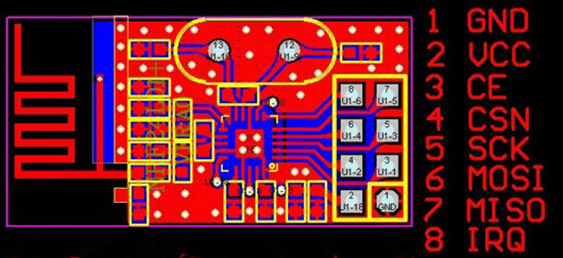
Step-by-Step: Our first step was trying to understand the pins on the nRF24L01. It has 8 pins in total: GND/VSS (Ground), VCC (power supply), CE (digital input RX/TX), CSN (digital Input SPI chip select), SCK (digital SPI clock), MOSI(digital SPI slave data input), MISO(digital SPI slave data output), IRQ (digital maskable interrupt pin).
First find: It ueses the Serial Peripheral Interface (short SPI), hence we need to look up what the default SPI pins on an Arduino are. Pin 10 (SS ), Pin 11(MOSI), Pin 12 (MISO), Pin 13 (SCK).
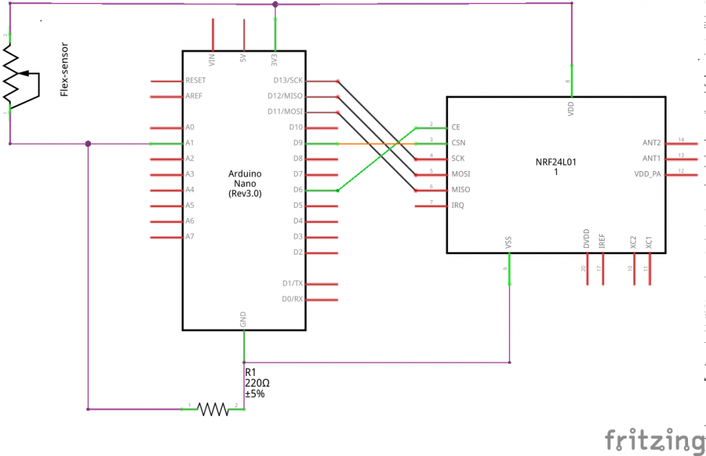
With that info. we can hook up our Arduino and the nrf24L01 since we now only need to match our ports.
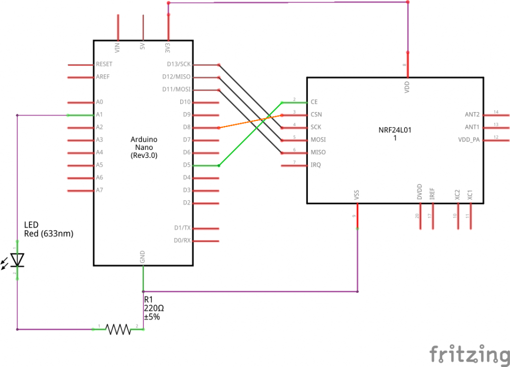
We modified the simple sketch by adding in a sensor on one side and an LED on the other. Now the only thing left to do for the initial task would be connecting both nRF24L01. For this we worked in the Arduino IDE.
The first snippet of code is our sensor rig, which sends its sensor-data to the other nRF24L01 that is defined by the second code. For this there is primaraly only one thing to keep in mind. One nRF24L01 sends, the other resieves. If the roles are to be switched one has to specifically stop the old role nad start the new one. Since we did not do this, we just have to focus on the communication. To make it work there are only a couple of steps needed. Both need to communicate on the same Pipe, you need a sender and resiever and you need to know how big the thing is you are trying to send. Done the rest is fancy stuff.
Source: Authors: Jun Ikeda Kobe University, Kobe, Japan Yoshinari Takegawa Kobe University, Kobe, Japan Tsutomu Terada Kobe University, Kobe, Japan Masahiko Tsukamoto Kobe University, Kobe, Japan
MoMM ’09 Proceedings of the 7th International Conference on Advances in Mobile Computing and Multimedia, Pages 105-112, Kuala Lumpur, Malaysia — December 14 – 16, 2009 ACM New York, NY, USA
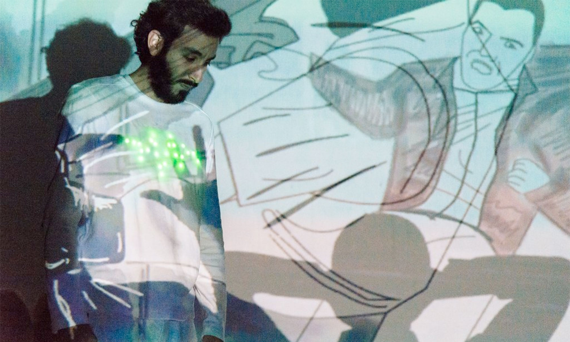
Summary: Lately the performances are getting more attention when they use computer technologies. Performances with a person having some sort of interaction with projections are very entertaining to watch.
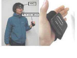
This article talks about the evaluation and experimentation of interactive performances using a projector. The goal of this article is to improve the way the performers are interacting with the projections and to support them using display devices like HMD.
In the entertainment world, the interactive performances are much known and there is always the desire to explode their potential. The idea is always to improve the performance itself. But this research is about supporting the performer.
In this article, the authors try to find the main problems on stage so they classified the performances in two principal types: the first one is when the projection is basically a movie and the performer has to memorize everything in order to perform in time. And the second type of performance is when the projections are based on the performer actions.
The article also mentions the situations a performer can face WHEN the performance is: facing the audience, facing the screen, in parallel with a screen, in contact with a screen, far from a screen and when using part of the body. In most situations the performer has difficulties to see the entire projected image.
Some display devices (HMD, Monitor, Projection on floor, Earphone) where took into consideration and they mention they pros and cons. At the end they choose the HMD because is the most effective and they adapted it as a display device, additionally they added a wireless mouse to the experiment. They made performers play some games using the HMD and the wireless mouse in order to evaluate the recognition speed, understanding of the object position and timing recognition of changing images. At the end the results vary, sometimes the problem was the delay in displaying images.
Other evaluations were: to see the naturalness of the performer when facing the audience, when the performer is far from the screen and is using a real object and when he/she touches the screen. In conclusion they found out their method is effective but they want to improve it and try similar works but with more than one performer.
Relevance for our project: This article is very relevant to our project. I see this article as a piece of advice. I am sure this research can help us with the developing of our ideas and with finding/creating hardwares we may need.
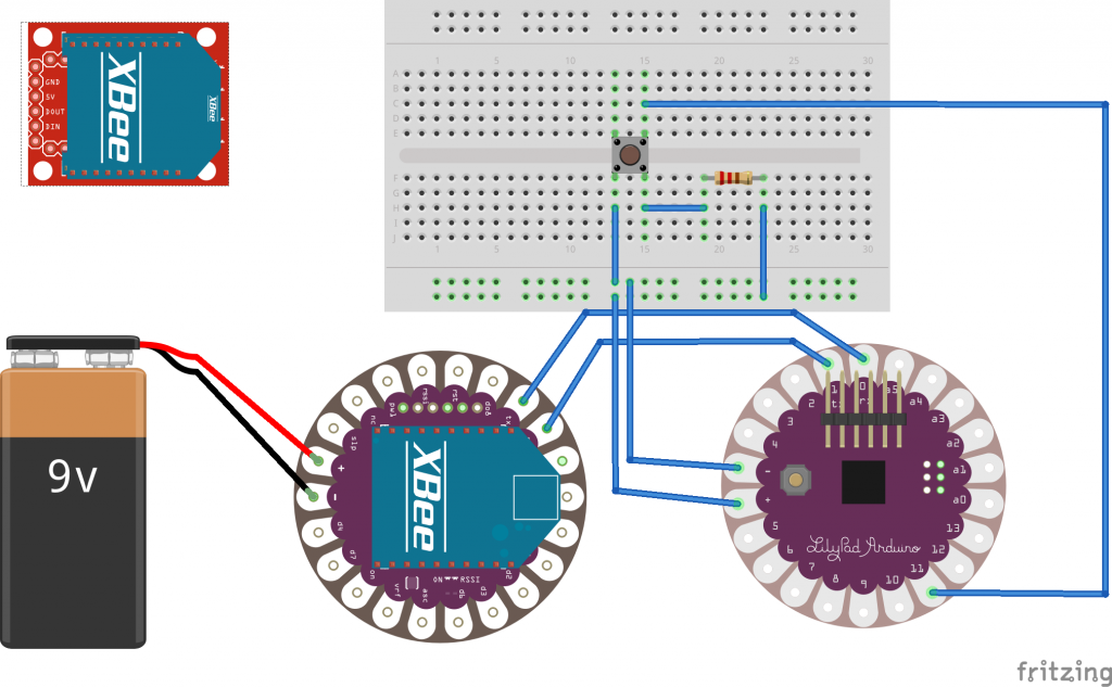
This simple tutorial documents our first Costumes and Environment work. A wireless connection is fundamental to connect a dancer or actor to its environment. The Xbee-Technology is one possibility to send sensor data, collected by the Arduino Lilypad to the computer.
We used the following components:
Hardware:
LilyPad
LilyPad Xbee
Xbee S1 x2
Xbee USB Shield
Software:
Arduino IDE
Processing
XCTU
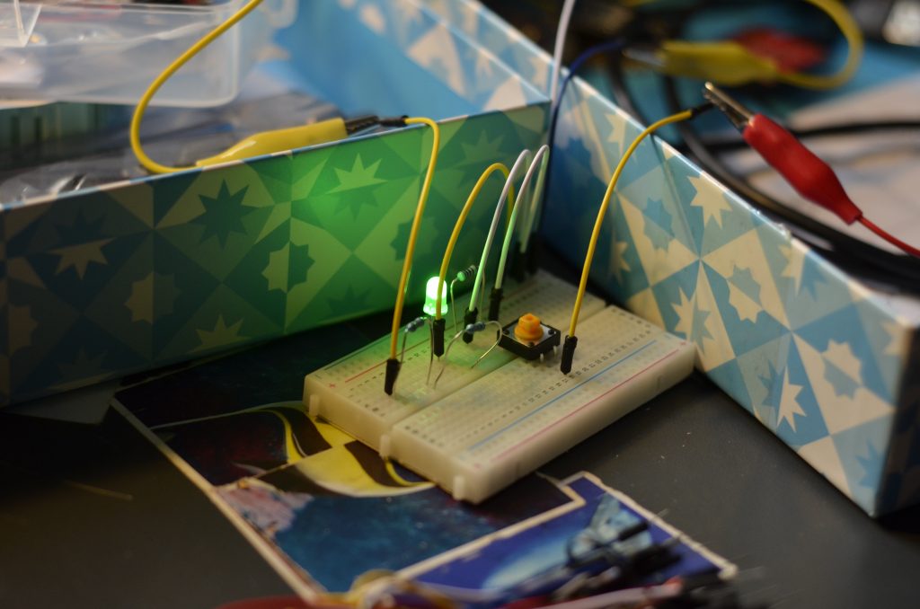
The result looks like this:
Whenever the button is pressed, the Lilypad sends a serial message to the Lilypad-Xbee-Component. That message is transmitted wirelessly to the other Xbee-Component, which is connected via USB to the Computer. In processing, the message can be read like an event. In our case a visual entity, a circle, simply changes destination.
01-Step-by-Step-Tutorial:
a)At first, we should create a simple Lilypad-circuit, to collect sensor-data. For example a pushbutton: https://www.arduino.cc/en/Tutorial/Button Any circuit is fine, as long as we can determine a state(Serial-Monitor: 0, 1 or whatever).
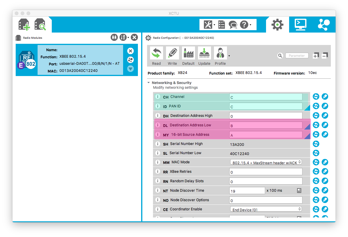
b)Now it is time to configure your XBees. You connect each XBee at a time via USB to the Computer and edit it in XCTU. You want them to communicate in the same channel(For Example C). Furthermore the source of each XBee should be the destination of the other XBee.
XCTU: Configure Xbee
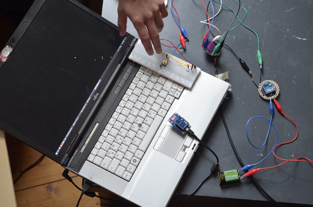
c)We can integrate the XBees in the circuit. The XBee-Lilypad-Shield should get at least 3.3V(we used a 9V blockbatterie). Furthermore you connect the Arduino Lilypad rx with the Xbee-Lilypad-Shield tx and the other way round, so that ones serial input(rx=receive) can receive messages from the others serial output(tx=transmit). The USB-XBee simply has to be plugged into the PC. We prefer that modular way of connecting, to keep things replaceable and (de)composable!
We don’t want an LED to blink, when we press the button, so we modify the Arduino Code and communicate with the XBee:
...
void setup() {
  Serial.begin(9600);
  pinMode(11, INPUT);
}

void loop(){
  int button = digitalRead(11);

  //Checks if button is pressed
  if (button == 1){

    //When input availabe, it prints
    if(Serial.available()){
      Serial.println("Button Pushed!");
      delay(1);
    }

    //Onboard LED Blinks if there is no Input to receive
    digitalWrite(13,HIGH);
    delay(250);
    digitalWrite(13, LOW);
    delay(250);
  }

  else {

    //Prints Stuff if nothing is received
    if(!Serial.available()){
      print_mh();
      print_pon();
    }

    //Prints Input if there is some
    else if(Serial.available()){
      Serial.println(Serial.read());
      delay(100);
    }
  }
}
d)Now we should build a simple processing Sketch. We simply used an older sketch of mine, which looks quite complicated. But any sketch is fine, as long as it works! For example a simple keyboard input-sketch: https://processing.org/examples/keyboard.html
Anyway, that is my sketch:
wechsel.pde is a processing sketch, with simple circles(entities). They interact via reciprocal attraction. Furthermore their behavior is influenced by random noise. Usually I control a special entity with mouse or touch. -Phil
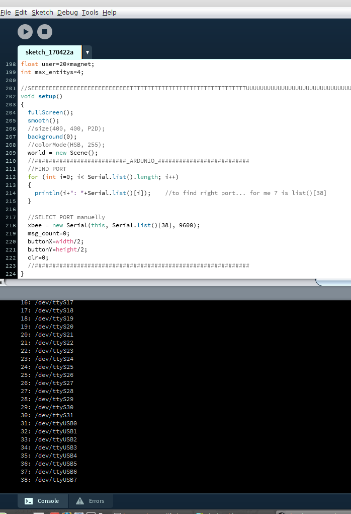
e)Now I want to integrate the XBee to Processing. In the Setup, we have to find the right port. So you check processing’s console for your USB-Port. Than you have to configure your code to fit to your port!
import processing.serial.*; //To work with the serial XBEE
Serial xbee;                //Declare XBEE
...

void setup()
{
 ...
  //FIND PORT
  for (int i=0; i< Serial.list().length; i++)
  {
    //Check console and search for your USB-Port
    println(i+": "+Serial.list()[i]);
  }

  //SELECT PORT
  //In my case, Serial.list()[38] is the right port..
  //You have to check your console and enter your Port here
  //manually!
  xbee = new Serial(this, Serial.list()[38], 9600);
  //Your Baud-Rate should be the same in Ardunio and
  //Processing, for example 9600!
}
...
See the Console:
Furthermore, we need a Free-Event-Function, that is acivated, whenever the XBee receives something.: