For the performance on the stage, we have been trying to find a plane seat around us / at the University. Yet, we were not allowed to take it for our project. As a result, we have been trying to find seats with reasonable price online.
A Student Project of the HCI Group | Bauhaus-Universität Weimar
For the performance on the stage, we have been trying to find a plane seat around us / at the University. Yet, we were not allowed to take it for our project. As a result, we have been trying to find seats with reasonable price online.
For some reason video editing programs tend to place a black frame at the end of the rendered clip. I really don’t know why, but that seems to be the usual thing. In my case that is kind of annoying, due to the fact, that I want to loop the video in unity.
After checking out several editing softwares, I ended up in the Ubuntu terminal:
ffmpeg, a command line video editor helps!
Use the first command to make your .mp4 to thousands of .jpg’s.
ffmpeg -i video.mp4 -qscale 0 scene%05d.jpg
By hand, you can easily delete the last frame…
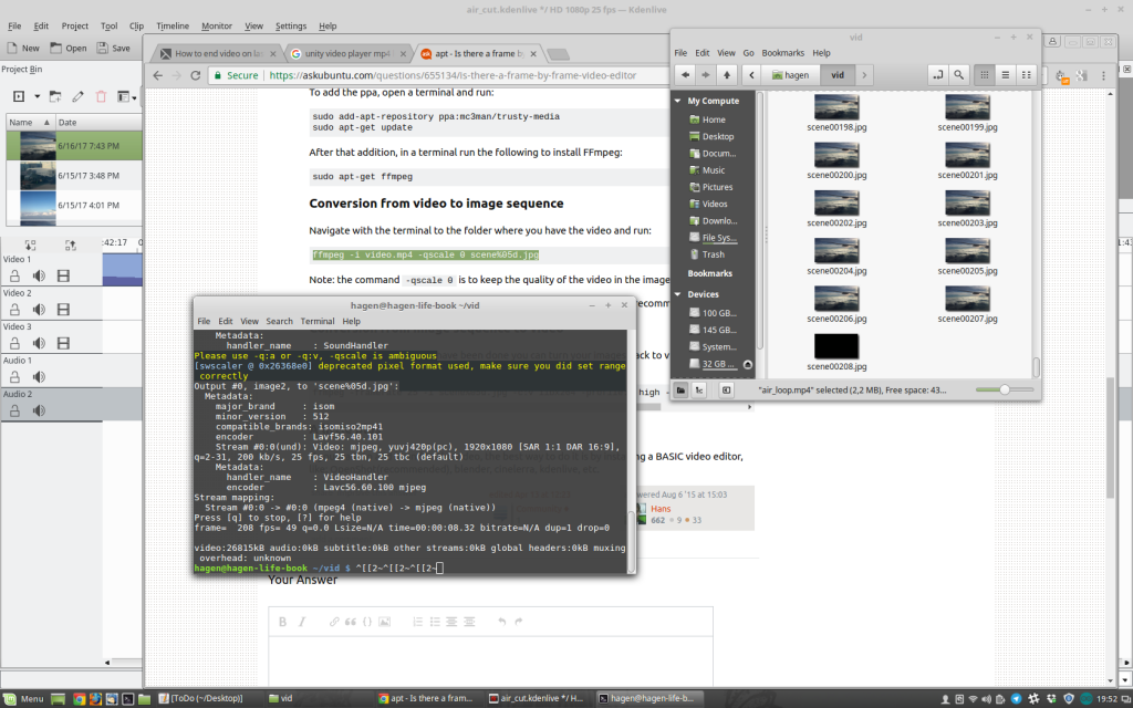
With the second command, you can take all your frames back into a .mp4.
ffmpeg -framerate 25 -i scene%05d.jpg -c:v libx264 -profile:v high -crf 20 -pix_fmt yuv420p newvideo.mp4Than you end up with a mp4, without a black frame at the end! Such a nice work-around, Cheers!
Just some free Airplane take off landing videos
Airport
https://www.videezy.com/transportation/4301-dolly-shot-of-a-plane-getting-ready-to-fly-4k-stock-video ([ martin popvski] Videezy.com in credits)
Take off
https://www.videezy.com/transportation/665-airplane-lift-off ([ SuperEzFilms] Videezy.com in credits)
Rising
https://www.videezy.com/travel/6960-stratus-or-stratocumulus-clouds-from-plane-that-is-banking-left ([Brandon Hoe] Videezy.com in credits)
In the air
https://www.videezy.com/transportation/1488-free-airplane-wing-hd-stock-video ([marco puccini] Videezy.com in credits)
epic in the air
https://www.videezy.com/travel/6873-view-of-clouds-and-plane-wing-at-dusk
clouds air
https://pixabay.com/de/videos/flugzeug-flugzeugfl%C3%BCgel-reisen-2283/
landing
https://pixabay.com/de/videos/flugzeug-reise-fenster-bullauge-995/
https://archive.org/details/naAirplanelandingairplane2wmv
https://archive.org/details/pp_landing
https://archive.org/details/youtube-1hEf96ZTssE (14.15, licesne?)
landed: https://pixabay.com/de/videos/asphalt-flughafen-turbine-gep%C3%A4ck-6414/
(not useful, but interesting black and white material: https://www.pond5.com/stock-video-footage/1/airplane.html?free=1#3/18447/pricelt:25,airplane)
I found a couple of webpages where we can apparently free Download clips that may be helpful for the performance
Weapons-sound:
http://www.audiomicro.com/free-sound-effects/free-guns-and-weapons
Fight-sound:
https://www.freesoundeffects.com/free-sounds/fight-sounds-10034/
Scream-sound:
http://soundbible.com/tags-scream.html
Muezzin:
http://freesound.org/people/AcousticYorick/downloaded_sounds/
For the airplane seat, we have asked m18 staff if we can borrow the seats from them. And we are still waiting for the answer.

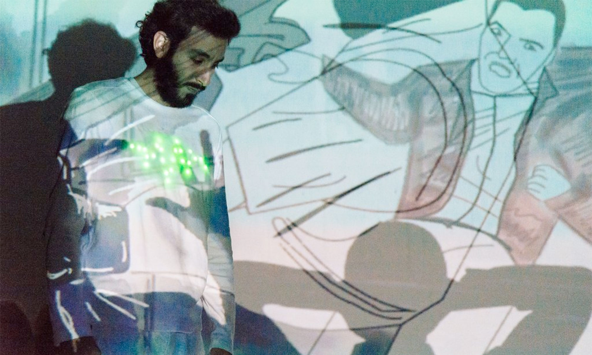
And here is Neo pixel and we are trying to figure out how to use fiber optics.

Experimentation with neopixels and optical fiber
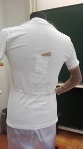
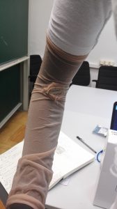
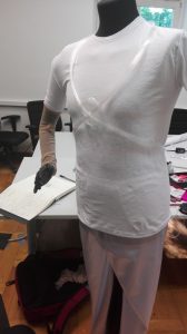
In the pictures below we can appreciate the first costume model with a small bag in the back for the feather HUZZAH esp8266 and another one un the arm for the accelerometer.
Here are a couple of videos of our experiments:
A short status-update:
the original plan:
Lucas primary developed the BLE(Stage)->Arduino(Costume) part:
We decided to work with the HM-10 modules, or so we thought. After some frustrating hours of not getting stuff to work, I noticed we don’t actually have HM-10 modules infront of us but rather HM-10 CC2541 modules, which are copys of the original. There is a diffrence however, all the At-commands have to end with „\r\n“ and the „?“ ending does not exist.
After figuring that out I looked up all the At-commands that the module offers. Nothing usefull to be found for our project, so I tryed uploading the original HM-10 firm-software to the CC2541. For this I took a look into this repository and the manufecturer site jnhuamao. I got myself the arduino code from the git-repository and uploaded it onto my Arduino Uno R3. Then I downloaded the CCLoader_x86_64.exe. From the manifacturer site I downloaded firmsoftware V540. One can download the latest version V549 and instead of useing the „AT+DISI?“ command to search for Beacons RSSI, you could use „AT+DISA?“ to search for all devices RSSI. For a more specific insight, one should look into the patch loggs, since there were other small but handy changes. Never the less, since I wanted to scann for Beacons, there was no need to get a later version then V540.
Now all thats left is the Hardware aspect. For this I cut the BLE modul out of its case and connected the Arduino VCC to Modules VCC, GND to GND, D6 to DD, D5 to DC and D4 to Reset. Not knowing which pin is which I took a look into the datasheet of the BLE-module. Run the CCloader_x86_64.exe from command line like this: path/CCLoader_x86_64.exe <COM Port> <path/Firmware.bin> 0. Done, now I had the HM-10 software on the CC2541 with the commands I opted to use.
Now to the actuall task, scanning RSSI of Beacons around. For this the „AT+DISI?“ command is helpful, since it returns 5-parameters, of which the fifth is the RSSI value of the device specified by its MAC-Adress (parameter 4). For this Command to actually work I needed to configure the BLE-Module, by running these commands first: „AT+ROLE1“ asigning Master role, „AT+BAUD0“ setting same baud as both Serial ports, „AT+RESET“ restart to aply changes, „AT+SHOW1“ show name, „AT+IMME1“ set worktyp. For further insight, datasheet is your best friend. Now i am able to run the „AT+DISI?“ command. The resieved answer from the BLE-module now only has to be parsed and filterd (see code) and vola, we now resieve the RSSI values of our specified devices.
For the connection Arduino-BLE module see here. Only diffrence mySerial(2,3) changed to mySerial(12,14). Change circuit accordingly.
Source code: Arduino code
Phil focused on the Arduino(Costume)->Unity3D(Computer) part. At first, we intended to use BLE, to achieve a communication between costume and Unity3D. Unfortunately the combination of Unity3D/C#/Windows and BLE seems to be a kind of unexplored thing. I was not able to find a good solution. There are some libraries to use mobile(android, ios) BLE with Unity3D(which actually cost money), but that does not help us. So I dropped back to the Adafruit Feather and its Wifi-Module. Maybe the costume will be controlled by the Feather as our primary micro controller, or we stick with the Arduino Nano and attach a seperate Wifi-Module. We will decide about this later. The problem with the Feather is the number of analoge pins, exactly 1… Anyway I was able to set up a server in Unity and receive sensor values. The video’s intensity can already be manipulatet by the RSSI values. My next step is, to seperate the video-framerate by the feather’s send-rate. I will consider using an asynchronous connection. Furthermore I have to get the other video-manipulations working. I will probably make use of Video-Textures in Unity3D!
Source code: Unity3D code
The Feather-client-connection part can be found in Lucas Arduino-sketch.
And some more BLE Links..:
https://blog.bluetooth.com/proximity-and-rssi
https://shinesolutions.com/2014/02/17/the-beacon-experiments-low-energy-bluetooth-devices-in-action/
https://community.estimote.com/hc/en-us/articles/201302836-How-precise-are-Estimote-Beacons-
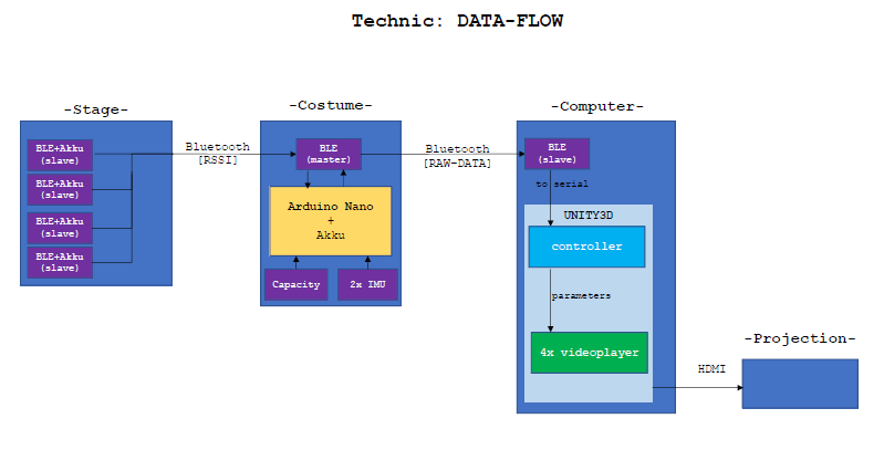
Our project technic has to cover all the way from input(sensor) to output (actuator). To give the actor freedom, we need a wireless transmission. For this we chose the following hardware, software and our interaction modle.
| Input |
|---|
| Sensors: |
|
| Microcontroller |
|
| Transmitter |
|
| Output |
|---|
| Receiver+Computation (pc) |
|
| Actuators (beamer, speaker) |
|
Concept:
The interaction idea is as follow. The „play“ is structurable into three parts: (1)Intro, (2)story/flashbacks, (3)Outro. Starting at (1), which is somewhat a basic projection state, all we are going to need is a way to switch to (2). Herefore a simple capasity sensor would be enough to signal the transition to (2).
Since (2) is the main interaction state or rather more the main objective for sensoric, we are going to have most hardware resulting from here. The basic setup is a rectangle out of BLE-Beacons in which the preformer is allowed to move. These four Beacons basicly represent the four flashbacks. So we now have a rectangle with a flashback asigned to each corner. For the projection, we are going to have one projectionspace on which we are going to project all flashbacks simultaneously, layering them over eachother so to speak. Since the flashbacks are asociable with a location, we are going to use this for our translation. Thought is, depending on the distance from preformer to flashback, the resulting trensformation of the projection is intensified or lowerd. So if the preformer closes distance to a corner, all his/her actions maniulate this corners falshback more then the others. Now the question would be how and in which way can the preformer manipulat the projection. Basic effect are going to be transparency, speed, color and brightness. These are going to be measured by onbody sensoric. For speed we are going to use an IMU located at the arm. This is going to be used for acceleration and tilt. The faster the preformer moves his/her arm in a cirtain direction, the faster the playspeed will get, vis versa for slowing down. An other IMU will be located on the back of the preformer. Once again with tilt and accereration to measure. This module will be responsible for color and/or brightness as to how the upperbody is located in space. If the preformer is bended forward(darker) or upright(lighter). In adition to the IMU on the back, we are also installing our cumpotational unit, the arduino nano plus the BLE-module. The BLE-module is going to be responsible for RSSI resival on comercial frequencies and the transmition of your data to our PC.
Lastly we are going to have to be able to switch to (3). Again our capacity sensor will have to fulfill the task.
We are currently trying to establisch a connection between our PC and our Arduino. For this we are trying to use a bluetooth transiever, the HC 05. In our first attempt, we useing the HC 05 as a receiver, which reads input data from our computer.
Hardware:
First things first, we need to setup our devises. Here the resistors are 100 Ohm each. This is due to the TX/RX needing 3.3V. Also keep in mind, that the RX goes to TX and vice versa.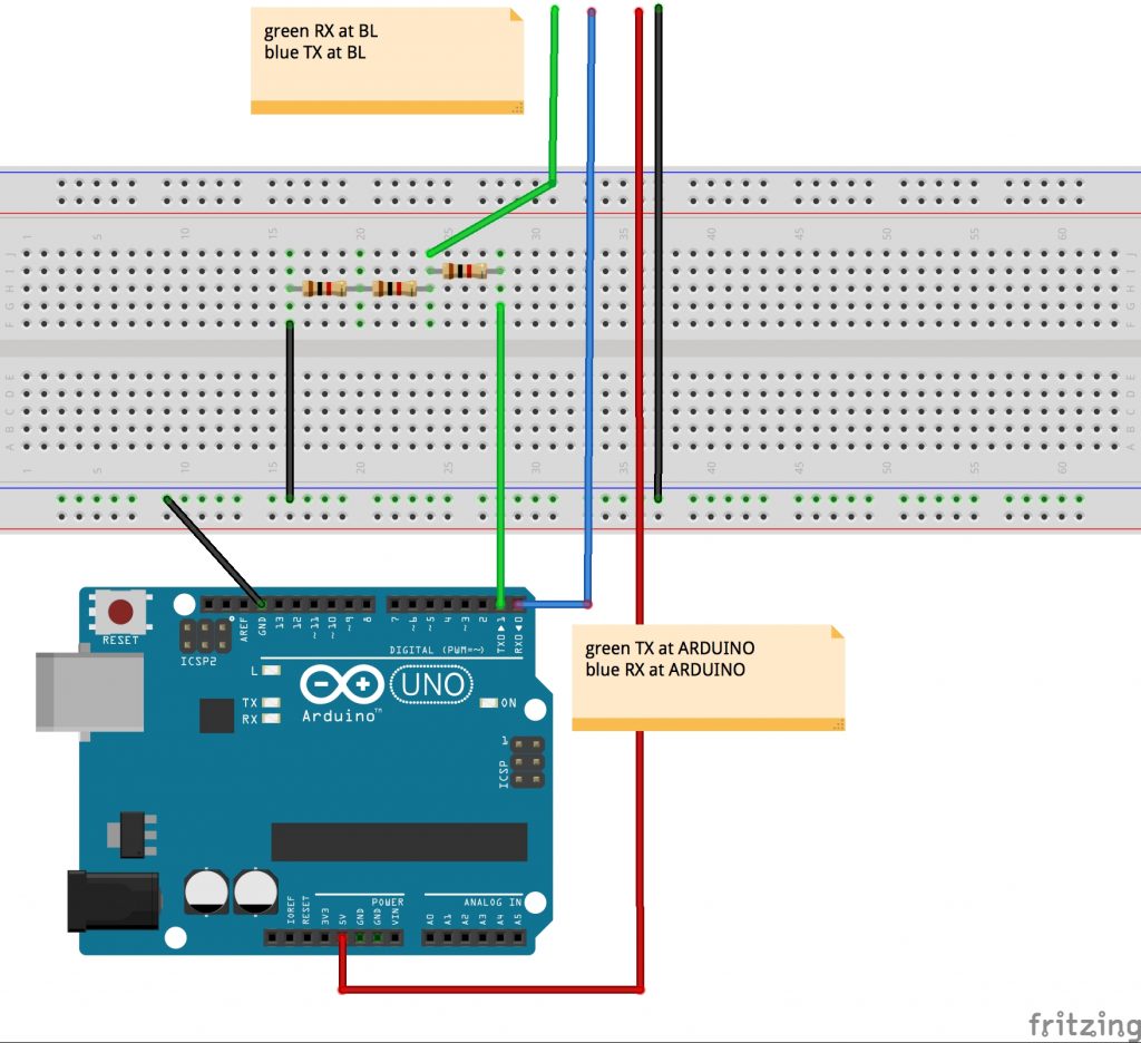
Once we’ve got the setup, its time for the software. Herefor we are useing Processing on PC (Win 10) to send and the Arduino IDE for the recieving arduino. Later on we are going to do it the other way around.
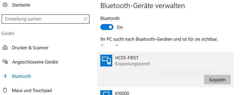
Step two would be pairing with the bluetooth device we just hooked up to the arduino. Under Win10 you can achieve it like follows:
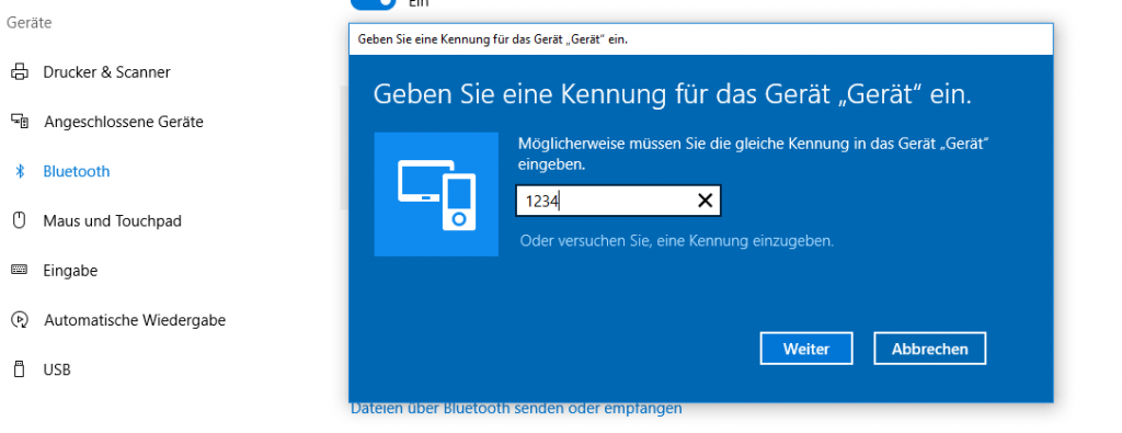
Now we have a finnished setup and its time for some code. Since our first objektiv is sending data to our arduino, it needs to be able to recieve it. For this code to work move the TX pin to pin 8 and the RX pin to pin 7!
#include <SoftwareSerial.h>
SoftwareSerial mySerial(7, 8);

void setup() {
  Serial.begin(9600);
  mySerial.begin(9600);
}

void loop() {
  char to_read;

  //while there is a signal from our HC 5
  //print it!
  while (mySerial.available()) {
    to_read = mySerial.read();
    Serial.print(to_read);
  }
}
In the code above, the arduino recieves data via the Serialports und prints it. The counter part would be the PC sending data via Processing. This looks as follows:
import processing.serial.*;

//Serial port object:
Serial arduino;
final int  baudRate   = 9600;
final char delimiter = '\n';

void setup() {
  //list all the available serial ports:
  println("Available Serial Ports:");

  //Choose your Bluetooth port:
  printArray(Serial.list());

  //and enter its position here:        🢃
  final String portName = Serial.list()[2];
  println("\nOpening Serial Port: " + portName);

  //Create instance:
  arduino = new Serial(this, portName, baudRate);

  size(500, 500);
  textSize(16);
}

void draw() {
  background(0);  //window: black
  text(str(mousePressed), mouseX, mouseY);

  if (mousePressed) {
   arduino.write('a');
  }
}
This code was provided by Johannes Deich. What it does is open a window which tracks your current mouse position and when you left-click it writes ‚a‘ to the serialport.
All done, we have now established the connection and are sending information from PC to Arduino!
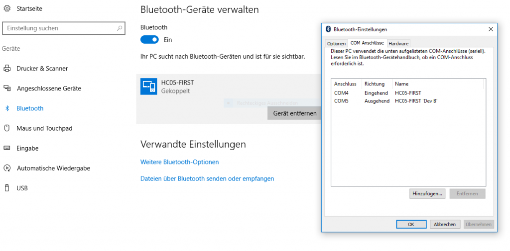
Now its time for the other direction, PC recieves data sent by the Arduino. The setup is exactly the same, only that now we have an incomming port, „COM4“ (See picture „Step 3“). Connect PC to bluetooth device as shown above and keep the current Bluetooth circuit. Again we are going to work with the Arduino IDE and Processing, since it would be nice being capable to merge both communication ways, since the only diffrence is the sofware code aspect. Here the arduino code looks as follows:
//We are only going to print on
//our Serialport, nothing else

void setup() {
  Serial.begin(9600);
}

void loop() {
  for(int i=0; i<9; i++){
    Serial.print("data ");
    Serial.print(i);
    Serial.print('\n');
  }
  delay(100);
}
On the arduino side of things, we only have to print what we want to send on the Serialport. In Processing it looks a little different:
import processing.serial.*;


Serial arduino;
final int baudRate   = 9600;
final char delimiter = '\n';

String serialStringFromArduino = null;

void setup() {

  //list all the available serial ports:
  println("Available Serial Ports:");
  printArray(Serial.list());

  //look on which port your divice is running
  //and enter it here                   🢃
  final String portName = Serial.list()[2];
  println("\nOpening Serial Port: " + portName);

  //create instance:
  arduino = new Serial(this, portName, baudRate);
  arduino.bufferUntil(delimiter);

  size(500, 200);
  textSize(16);
}


void draw() {
  background(0);

  //render String as text in window
  if (serialStringFromArduino != null) {
    text(serialStringFromArduino, 20, 40);
  }
}


void serialEvent(Serial arduino) {
  //read string:
  serialStringFromArduino = arduino.readString();

  //remove amongst other things whitespace and carriage return
  serialStringFromArduino = trim(serialStringFromArduino);
}
Once again we have nearly the exact same code (from Johannes Deich), manly since 95% of it are for the selection of the right port. If one already knows the port on which the Bluetooth device is running, one doesn’t need that part of the code. The rest of the code is just parseing the recieved data String. Vola, all set and done for basic Bluetooth communication.
In contrast to Xbee, WIFI-Feather and NRF technology, the Bluetooth technology makes it easier to connect to the computer(if the computer has Bluetooth). We don’t need a USB-Xbee Shield, a LAN-Router or another NRF-Module+Arduino->connected to the computer.