Unity: realt-time videomanipulation

Is Unity a solution to manipulate videos in real time?

People used to use Movie Textures, but now the new VideoPlayer is available. So I tried some simple tests.

UNITY-C#-Script

using System.Collections;
using System.Collections.Generic;
using UnityEngine;
using UnityEngine.Video;

public class player : MonoBehaviour {

 //drag & drop costume-controller:
 public GameObject costume;
 //we will use 2 vid-player
 private VideoPlayer videoPlayer1;
 private VideoPlayer videoPlayer2;

 void Start()
 {
 //get Cam
 GameObject camera = GameObject.Find("Main Camera");

 //add to videoplayer
 videoPlayer1 = camera.AddComponent<UnityEngine.Video.VideoPlayer>();
 videoPlayer2 = camera.AddComponent<UnityEngine.Video.VideoPlayer>();

 //select RenderMode
 videoPlayer1.renderMode = UnityEngine.Video.VideoRenderMode.CameraNearPlane;
 videoPlayer2.renderMode = UnityEngine.Video.VideoRenderMode.CameraNearPlane;

 //set alpha
 videoPlayer1.targetCameraAlpha = 0.5F;
 videoPlayer2.targetCameraAlpha = 0.5F;

 //set absolute path
 videoPlayer1.url = "/Users/Hagen/Documents/unity_projekte/video_2d_test/Assets/vidtest.mp4";//DSC8538.MOV";
 videoPlayer2.url = "/Users/Hagen/Documents/unity_projekte/video_2d_test/Assets/airplane2.ogv";//DSC8538.MOV";

 //we want a flashback-loop
 videoPlayer1.isLooping = true;
 videoPlayer2.isLooping = true;

 //start players!
 videoPlayer1.Play();
 videoPlayer2.Play();
}

void Update()
{
 //edit alpha using the costume controller variables:
 videoPlayer1.targetCameraAlpha= costume.GetComponent<controller>().intens_b;
 videoPlayer2.targetCameraAlpha= costume.GetComponent<controller>().intens_a;

 //edit video speed
 videoPlayer1.playbackSpeed= costume.GetComponent<controller>().speed_a;
 videoPlayer2.playbackSpeed= costume.GetComponent<controller>().speed_b;
 }
}

By changing the floats intens_a, intens_b, speed_a and speed_b. The video gets more or less transparent and faster or slower. I used simple archive footage:

https://archive.org/details/Pbtestfilemp4videotestmp4

https://archive.org/details/naAirplanelandingairplane2wmv

It already looks very flashback like. For now, I am quite happy that it is manageable to use Unity to real-time play and manipulate videos. The most important functions work already. Later on I will try to manipulate brightness and color. At the moment there is a small problem with the alpha-transparency. I intended to add all the pixels up, to achieve a symmetrical transparency. So if all loops are played in full intensity, we can see all pictures and the result might be quite bright. At the moment, the video players are layered, so we only see the front-player, due to the fact that its transparency is zero. But I guess we can work around this somehow(Maybe we have to use Movie Textures..) Interesting will be, how high our video resolution can be and how many flashbacks can be played at the same time.

The next step will be connecting the arduino(costume) to Unity.

Initial Post: Memories of a Syrian Student

So this is our initial post, documenting the work of the project: „Memories of a Syrian Student“

0. What happened before?

After the literature and technology research, we had a bit of struggle defining the goal of our project. We knew quit early, that we all wanted to work together as a big team:

To find the right idea is kind of difficult in such a open project. Clear is, we want a costume with sensors, wearen by a performer, manipulating a stage. Do we want a dance-performance, a theater-scene or another scenario? How can we combine all our skills in the best way? Do we want to craft physical objects, control stage equipments(lights, stage elevator,…) or manipulate audio-visual media?

At first we were thinking of a physical object, a cloud flying like a spider cam over the actor, with several interaction features, showing the protagonist’s mood.

Example of SpiderCam System:

After a few weeks of research, we realized, that the top scaffold could be difficult without drilling in the ceiling and that the big step motors would surpass our budget.

Keeping that cloud concept alive, we thought about a full-cloud-ceiling in order to not have to worry about motors.

There were several problems too, the system would not be transportable, it would be difficult to find a craft/installation-space, it could be hard to integrate the audience,…

So we came up with new ideas. We took the focus more on costume design and visual projection.

1. What is happening?

Now we have a stage performance art concept with the working title „Memories of a Syrian Student“:

Our Student is just on the flight from Syria to Germany.  Our Scenario covers the time between take off and landing. With a projection, we visualize his memories. The actor walks through his flashbacks(Video-loops). By his movement and acting, he controls/manipulates the projection using his costume.

At the moment, Joeng and Phil develop the script. Laura and Joeng develop the stage+costume design and a storyboard. Lucas and Phil set a sensor->actuator list, try to manipulate video-loops and estimate whether Bluetooth communication could serve as an advantage.

Yesterday I shot some example pictures showing the stage with moody projections:

The old stage-model by Jeong & Laura:

(projection picture found at http://cdnfiles.hdrcreme.com/1805/medium/bazzar.jpg?1426885632)

The new stage-model for projections by Jeong:

(projection picture found at http://www.liveshoptravel.com/wp-content/uploads/inside-airplane.jpg)

(projection picture found at https://media1.s-nbcnews.com/j/newscms/2015_41/1250486/151006-palmyra-jpo-627a_128818d31c6c46f432a80b57026affb7.nbcnews-ux-2880-1000.jpg)


The static stage-model by Laura with all the flashback scenes in the back and possible objects on stage:

2. What will happen?

From now on, each step will be posted in the project-category.

There is obviously still a lot to do, some questions are:

  • Who will be the actor?
  • Who is going to make the off-stage voice?
  • Will the projection be archive-footage, self-made/drawn material or a 3D Animation?

Fashionable Magic Act’s Quick Changes Amaze the Audience

Sos & Victoria: Fashionable Magic Act’s Quick Changes Amaze the Audience – America’s Got Talent 2016.

A married couple marries fashion and magic for an amazing stage show.

The Story about Sos & Victoria Petrosyan

Sos and Victoria Petrosyan are performing an extraordinary act. And they‘re fast – very fast. They have to be, since time is always working against them.

Hardly ever before the art of quick change magic has been seen as perfect, as professional and as elegant, not to mention their originality and sheer virtuosity.

Sos and Victoria Petrosyan have created a unique act, the quick change has become their signature piece. Although they are very active in other fields of magic, too: Just think of their truly poetic presentation of the floating and dancing cane. Or think of their most original interpretation of grand illusions. Another fine example is their version of the „little magician“.

Extra links:

http://www.sosmagic.com/

http://www.sosmagic.de/


Tutorial: Connecting Adafruit Feather HUZZAH ESP8266 wireless in real-time to Processing 3.3/Computer

00-Introduction:

The Adafruit Feather HUZZAH ESP8266 is a simple micro controller.  A big point of the Feather is the on board WIFI(no additional Modules+ no Wires needed )! In my case, the motivation is to have a thin and light micro controller to collect data on the costume and send it in real-time wireless to a computer and remote a theater-stage.

In this so called „Tutorial“, I will document my research and steps to establish a real-time server-client-communication(raw data) between the Feather as a WIFI Client and a simple Processing Sketch as a Server. The Feather collects Sensor Data(button press), sends it wireless to the processing server. The Server(Processing Sketch) changes its status and sends feedback to the Feather, which lights a LED after a successful communication.

The research was kind of difficult. There are some tutorials, but unfortunately no real-time communication tutorials. Due to the  fact, that I am new to Web-technology, my solution might be a bit unconventional? (You might leave a comment if that is the case). Anyway here is my solution.

01-Step-by-Step-Tutorial:

I used the following components:

BASIC-Hardware

Adafruit Feather HUZZAH ESP8266

A Network(WLAN-Router, WIFI)

A Computer

BASIC-Software:

Arduino IDE

Processing

a)At first, you should set up everything:

Here, we can stick to Adafruit’s Tutorial, it is very detailed. Here are the steps in short:

  1. solder the feather, to make it easier to plug cables to it
  2. update the Arduino IDE(http://www.arduino.cc/en/Main/Software)  to use the Board Manager
  3. integrate additional Board Manager(http://arduino.esp8266.com/stable/package_esp8266com_index.json)
  4. install the ESP8266 package using the Board-Manager
  5. choose the right board and port in Arduino IDE->Tools(Adafruit HUZZAH ESP8266)
  6. choose in Tools: CPU Frequenzy(„80Mhz“), Flash Size(„4M (3M SPIFFS)“), Upload Speed(115200 baud)

Now everything should be configured and you might want to check a simple sketch(LED Blink?) and a simple WIFI-Connection? At this point we have to build our own application, without the Adafruit-Server, to get the freedom of our own server.

b) Set-Up the Arduino-Client

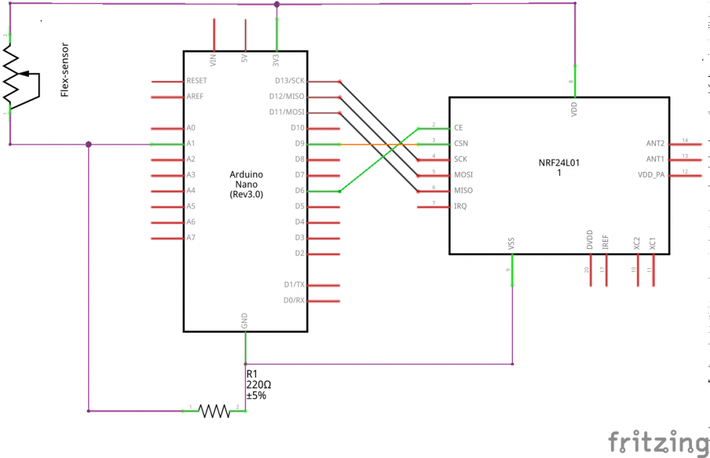
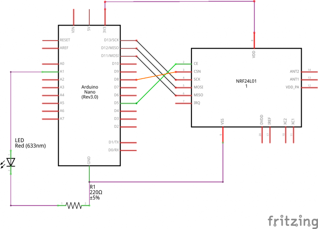
I use a simple Button-circuit as a sensor.(Button=1 if pressed) And I can control a LED:

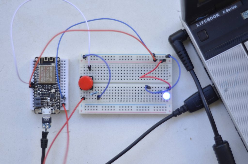
You can use any other sensor instead of a button and any other actuator instead of a LED.

My final code will look like this:

CODE-Arduino


//programm_specific
#include <string> //to use string
int pin_out_LED; //LED
int pin_in_BUTTON; //Button
int pressing; //remembers if button is pressed
int counter; //message_out counter
String msg; //message_out content
String line; //message_in content

//time_calculation
unsigned long time_a; //start_time
unsigned long time_b; //end_time
bool time_check; //are we interested in time?
bool received;

//Configure WIFI:
#include <ESP8266WiFi.h> //Wifi-li brary


//WLAN-Config
const char* ssid = "YOUR_WIFI_NAME_?"; //Your WIFI Name?
const char* password = "YOUR_WIFI_PASSWORD?"; //Your WIFI Password?

//Host&Client
WiFiClient client; //Feather as a client
const char* host = "192.168....IP_AD.."; //My Server(processing) IP Address(Terminal:"ifconfig -a")
const int httpPort = 12345; //Servers port


void setup() {

 Serial.begin(115200); //baud rate
 pin_out_LED = 14;
 pin_in_BUTTON = 12;
 pressing = 0;
 counter = 0;
 time_a = millis();
 time_b = millis();
 time_check = false;
 received = false;
 pinMode(pin_out_LED, OUTPUT);
 pinMode(pin_in_BUTTON, INPUT);

 // We start by connecting to a WiFi network
 Serial.println();
 Serial.print("Connecting to ");
 Serial.println(ssid);

 WiFi.begin(ssid, password); //Connect to WIFI
 digitalWrite(pin_out_LED, HIGH);
 while (WiFi.status() != WL_CONNECTED) {

 delay(500);
 Serial.print(".");
 }
 digitalWrite(pin_out_LED, LOW); //We are connected to SSID
 Serial.println("");
 Serial.println("WiFi connected");
 Serial.println("IP address: ");
 Serial.println(WiFi.localIP());
}

void loop() {

 if (!client.connected())
 {
 if (!client.connect(host, httpPort))
 {
 Serial.println("connection failed");
 delay(500);
 }
 } else {
 //Read Sensor
 if (digitalRead(pin_in_BUTTON)) //if( 1==digitalRead(..)) Button pressed?
 {
 if (pressing == 0)
 {
 counter++;
 if (counter > 100)
 {
 counter = 0;
 }

 msg = String(counter) + ": s \n\r";
 client.print(msg); //SEND to Server

 pressing = 1;
 time_check = true;
 received = false;
 }
 } else {
 pressing = 0;
 }

 while (client.available())
 {
 //READ SERVVVVVVVVVVVVVER
 line = client.readStringUntil('\r'); //READ from Server
 if (line.endsWith("1"))
 {
 digitalWrite(pin_out_LED, HIGH);
 received = true;
 } else if (line.endsWith("0"))
 {
 digitalWrite(pin_out_LED, LOW);
 received = true;
 }
 }

 //To calculate Send_Time
 if (time_check)
 {
 if (received)
 {
 time_b = millis();
 msg = String(time_b - time_a) + "transfer_time";
 Serial.println(msg);
 time_check = false;
 received = false;
 }
 }else
 {
 time_a = millis();
 }
 }
 
}

Whole project code, here.

1.Include, Declare,..

At first, I declare program-specific variables. To control the LED, I declare „pin_out_LED„, in setup I will set it to 14. To use the Button, i declare „pin_in_BUTTON„, in setup I well set it to 12, because of my feather-circuit. Additional I have to set the pin Modes: „pinMode(pin_out_LED, OUTPUT)“ and „pinMode(pin_in_BUTTON, INPUT)„. To remember whether the the button is pressed, I use „pressing„. A „counter“ counts the messages send by the feather. I use „msg“ and „line“ to send and read messages.

Furthermore I want to check the message-transmission-time with „time_a„, „time_b“ and „time_check„. Later more about this.

Now we have to get the WIFI working. In a) point 4, you should have installed the ESP8266, now we want to include it to our code(„#include <ESP8266WiFi.h>“) to make use of it. Manipulate the ssid by entering your WIFI’s name: const char* ssid = „YOUR_SSID_NAME_?“ and do the same with the password: const char* password = „YOUR_PASSWORD_?„. This will work for a simple WIFI connection, not with a special network, for example the university’s eduroam, where you need a username and password. For further information check here( Jan 07, 2017).  For me, a cheap router or my smartphone’s LAN worked fine.. We have to make the Feather as a client: „WiFiClient client“ . You need to know and enter your hosts IP-Address(const char* host = „192.168.1.33“) You need to check it at the computer, where your server(processing sketch) runs. A short research will help to find it. In Ubuntu/Linux, one can simply enter „ifconfig -a“ in Terminal to get it. Later in the processing sketch, we will define a port, through which we will communicate to the server. You can use this one(const int httpPort = 12345).

2.setup()

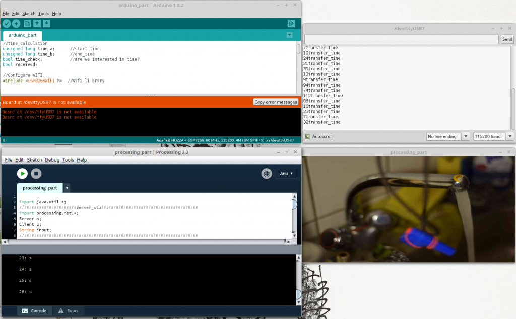
The setup() part is pretty much straight forward. We begin connecting to the WIFI and the LED is High and we print dots in the Arduino-IDE-Serial-Monitor(Ubuntu: STR+Shift+M), while it is connecting.

It should print: „Wifi connected“.

3.loop()

We always check, whether we are already or still connected to the server. „if (!client.connected())“ . There is a great difference towards the next if request: „if (!client.connect(host, httpPort))“  In contrast to the first, the second one always sends a new server connection request! We only need a new connection if we are not connected yet! Usually Client-Server communication uses client.connect(host, httpPort). A client sends a request and closes the connection, but we do not want to close the connection. We stay connected to save time! We don’t use the common HTTP Get Request, we will simply send RAW-Sensor-Data. That should be efficient and therefore better for real-time communication! At first I was not aware of the difference, I was only using the second one. After sending about 500 messages between server and client I received  „exception 29″ in the Arduino Serial-Monitor, because of memory overflow.  Furthermore processing warned „client got end-of-stream„.

Anyway if we can not connect to the host-server(processing) it will print connection failed. If we are already connected, the procedure can go on!

We only want to send a message, if(if (digitalRead(pin_in_BUTTON))) the Button is newly(if (pressing == 0)) pressed(I press once and hold it pressed, but I only want to send one message!) Whenever that is the case, we send a message(and make counter++, make a time_check,..):

msg = String(counter) + „: s \n\r“;
client.print(msg);

I will always send and receive with a \r at the end of the message, to make it easier to parse! To receive a message, we check whether there is an incoming message with client.available().  

line = client.readStringUntil(‚\r‘);

We read the message until ‚\r‘ and check, whether we received a „1“ or „0“ and according to this, we turn the LED HIGH or LOW.

In between, there is some time_checking. You might want to use or improve it? I get 4ms to 100ms transmission time and in average about 15ms.

c)Set Up the Processing-Server

Now I create a simple server on my computer, using processing .I want to receive a message sent by the feather/client to trigger(on and off) a virtual water faucet(older project of mine):

Whenever there is a change, I want to send feedback to the feather/client(feather lights the LED).

My Full-Code will look like this:

CODE-Processing

import java.util.*;
//#####################Server_stuff:####################################
import processing.net.*;
Server s; 
Client c;
String input;
//######################################################################

//Bilder:
ArrayList<PImage> bilder_a;
ArrayList<PImage> bilder_b;

int phase; //Aktuelle Bild-Nr
int direc; //An oder Aus?
int mode; //Focus
int pic_anzahl; //Anzahl an Bildern

void setup() {
 //Video:
 //fullScreen(); 
 size(600, 300);
 frameRate(25); 
 orientation(LANDSCAPE); //Bug?!

 //Load Pictures:
 bilder_a=new ArrayList(); 
 bilder_b=new ArrayList();
 pic_anzahl=9;

 String pic_name;
 for (int i=0; i<=pic_anzahl; i++)
 {
 pic_name="pic_a"+i+".JPG";
 bilder_a.add(loadImage(pic_name));
 pic_name="pic_b"+i+".JPG";
 bilder_b.add(loadImage(pic_name));
 }

 //Setting_UP:
 phase=0; //Wasser Bild 0
 mode=0; //Focus auf Hebel
 direc=-1; //Wasser auschalten

 //#####################Server_stuff:####################################
 s = new Server(this, 12345); // Start a simple server on a port
 //######################################################################
}

void draw() {
 //#####################Server_stuff:####################################
 c = s.available();
 //println(c);
 if (c != null) 
 {
 input = c.readStringUntil('\r'); 
 //input = input.substring(0, input.indexOf("\n")); // Only up to the newline
 println(input);

 if (input.contains("s"))
 {
 if (phase==0)
 {
 phase=1;
 //#####################Server_stuff:####################################
 s.write("1\r");
 } else {
 s.write("0\r");
 //######################################################################
 }
 direc=direc*-1;
 }
 } 

 //######################################################################

 if (phase>0) //Wasser läuft
 {
 if (phase>8) //Repeat:
 {
 phase=4;
 }
 phase+=direc; //Up or Down
 } 

 //Focus:
 if (mode==0)
 {
 image(bilder_a.get(phase), 0, 0, width, height); //Focus: Hebel
 } else
 {
 image(bilder_b.get(phase), 0, 0, width, height); //Focus: Hahn
 }
}

void mousePressed()
{
 if (mouseX>width/2) //switch foucs: Hebel/Hahn
 {
 mode++;
 mode=mode%2;
 } else //switch Wasser: an/aus
 {

 if (phase==0)
 {
 phase=1;
 //#####################Server_stuff:####################################
 s.write("1\r");
 } else {
 s.write("0\r");
 //######################################################################
 }
 direc=direc*-1;
 }
}

To make the faucet working, you need the whole project with pictures, here.

1.Include, Declare,..

I import processing.net.* to be able to use Server and Client!

2.setup()

I open a Server s = new Server(this, 12345);  at port 12345. You can change the port if you like.

3.draw()

To receive a message send by feather/client, we check whether there is an incoming message with c = s.available().  

If there is a message( if (c != null)), we read the incoming String until ‚\r‘:

 input = c.readStringUntil(‚\r‘); 

We check the input, whether it contains(„s“) and change the faucet’s state and transmit the changes back to the feather/client:

s.write(„1\r“);

The rest of the Code contains only my faucet mechanics.

I hope my tutorial helps people getting their real-time feather to processing application working!
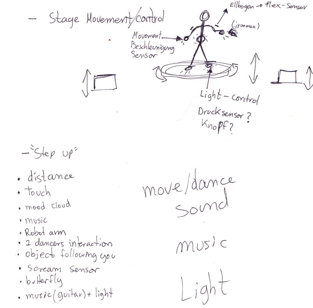
 

02-Some Ideas:

a)Just to answer some study-questions:

  • Yes, one can work without Adafruit’s Server(obviously I am using my own server)
  • no it is not just a close cloud communication system, I guess the feather is open, to work with like any web-application


b)Just to give some study-questions:

  • NodeMCU’s Lua or Arduino IDE to configure Feather?
  • How long is the battery lifetime while sending in real-time?
  • One could compare latency(time) and range in different Networks? (I only tried a simple router and my smartphone)
  • Should one preferably use UDP or TCP?
  • Switch roles? Feather as Server and Processing as Client?
  • How does our application work, if there is more traffic on the server?
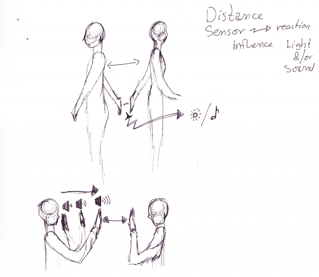
 

c)Further Ideas:

  • You could secure your connection, because everyone can read it the way it is at the moment. It might be interesting to observe the transmission vie TCP DUMP or Wireshark?
  • If the application stays that way and you only press the button/send a message once in a long while it might be necessary to send a heartbeat from time to time in order to keep the connection.
  • Instead of parsing Strings, we could send simple Bits or Bytes. That would make everything more efficient.
  • At the moment I am only sending when I press the button. It also worked, when I was sending ping pong like all the time.


MOODBOARDS

Inspirations-Ideas-Design

First Moodboard (concept & costume inspirations):

https://www.pinterest.de/laliraya/moodboard-my-t-shirt-is-my-remote-control/


Current Moodboard:

https://www.pinterest.de/laliraya/costume/


Extra links ( pictures found at): 

https://es.dreamstime.com/imagenes-de-archivo-ropa-del-blanco-del-hombre-joven-image36508034

https://es.123rf.com/photo_16794141_imagen-del-estudio-de-un-hombre-joven-y-guapo-posando-aislado.html?fromid=dHFNbjBIWFdqMVU0cXRqTTBycmZzdz09

https://www.fotolia.com/search?serie=81492962

Tutorial: Working with the nRF2401

Introduction: The nRF24L01 is a single chip radio module. Our task was to get two nRF24L01 up and running, connecting both and transmitting flex-sensor data. For this our hardware was:

  • 2x nRF24L10
  • 2x Atmega nano v3
  • 1x Flex sensor

Step-by-Step: Our first step was trying to understand the pins on the nRF24L01. It has 8 pins in total: GND/VSS (Ground), VCC (power supply), CE (digital input RX/TX), CSN (digital Input SPI chip select), SCK (digital SPI clock), MOSI (digital SPI slave data input), MISO (digital SPI slave data output), IRQ (digital maskable interrupt pin).

First find: It ueses the Serial Peripheral Interface (short SPI), hence we need to look up what the default SPI pins on an Arduino are. Pin 10 (SS ), Pin 11 (MOSI), Pin 12 (MISO), Pin 13 (SCK).

With that info. we can hook up our Arduino and the nrf24L01 since we now only need to match our ports.

nRF24L01 Sender-Schaltung
nRF24L01 Empfänger-Schaltung


We modified the simple sketch by adding in a sensor on one side and an LED on the other. Now the only thing left to do for the initial task would be connecting both nRF24L01. For this we worked in the Arduino IDE.

// SENDER CODE:
#include <RF24.h>
#include <nRF24L01.h>
#include <RF24_config.h>
#include <SPI.h>

RF24 radio(6,9);
int data[1];

void setup(void){
  Serial.begin(9600);
  pinMode(A1, INPUT);
  
  radio.begin();
  radio.enableDynamicPayloads();
  radio.setPALevel(RF24_PA_MAX);
  radio.setChannel(1);
  radio.openWritingPipe(0xF0F0F0F0E1LL);
}

void loop(void){
  data[0] = analogRead(A1);
  radio.write(&data, sizeof(data));
  Serial.print("Sent: ");
  Serial.println(data[0]);
}
// RESIEVER CODE:
#include <RF24.h>
#include <nRF24L01.h>
#include <RF24_config.h>
#include <SPI.h>

RF24 radio(5,8);
int data[1];

void setup(void){
  Serial.begin(9600);
  pinMode(A1, OUTPUT);
  
  radio.begin();
  radio.enableDynamicPayloads();
  radio.setPALevel(RF24_PA_MAX);
  radio.setChannel(1);
  radio.openReadingPipe(1,0xF0F0F0F0E1LL);
  radio.startListening();
  
}

void loop(void){
  
  if (radio.available()){
    boolean dump = false;
    while (!dump){
      dump = radio.read(&data, radio.getDynamicPayloadSize());
      digitalWrite(A1, HIGH);
      Serial.println(data[0]);
    }
    delay(100);
  }
  else{ 
    Serial.println("No radio available");
    delay(1000);
  }
}

 The first snippet of code is our sensor rig, which sends its sensor-data to the other nRF24L01 that is defined by the second code. For this there is primaraly only one thing to keep in mind. One nRF24L01 sends, the other resieves. If the roles are to be switched one has to specifically stop the old role nad start the new one. Since we did not do this, we just have to focus on the communication. To make it work there are only a couple of steps needed. Both need to communicate on the same Pipe, you need a sender and resiever and you need to know how big the thing is you are trying to send. Done the rest is fancy stuff.

Audiolizing Body Movement

Source

Naoyuki Houri, Hiroyuki Arita, Yutaka Sakaguchi. 2011. Audiolizing body movement: its concept and application to motor skill learning. In Proceeding AH ’11 Proceedings of the 2nd Augmented Human International Conference Article No. 13 Tokyo, Japan — March 13 – 13

Summary

This article deals with a project that transforms the posture/movement of the human body or human controlled tools into acoustic signals and feeds them back to the users in a real-time manner.

The author says that sound effect plays a very big role in our common lives and events: many artificial system such as Video game, Cell Phones, etc, have been proposed for displaying information through auditory channel. (it is common to add sound effect for enhancing realistic sensation, or to give a stronger image and signs through auditory events, which let our brain learn their correlation better).

However, body information such as posture, movement and muscle forces are insensible. And that is why audiolizing these gestures can be effective to enhance and sense our movement better. It is also another method to compare the body states of different individuals or identical person with different occasions.

Practice

  1. Asistance of Soldering Work (audiolization system measure temperature)
  2. Audiolization of Calligraphy (a 6-axis force torque sensor attached to a brush)
  3. Pole Balancing Game (3D posture sensor)
  4. Acoustic Frisbee (3D acceleration sensor)


Relevance

If we want to work with different sensors as feedbacks system to understand our gesture better (signal and sign of our gestures and movements), this article might be helpful to see how they used different sensors within different subjects and occasions. We can use it as inspirations.

Kinesonic Approaches to Mapping Movement

Source

MOCO ’15, August 14 15, 2015, Vancouver, BC, CanadaCopyright is held by the owner/author(s). Publication rights licensed to ACM.

ACM 978-1-450334570/15/08…$15.00
DOI: http://dx.doi.org/10.1145/2790994.2791020

Summary

This project introduces RAKS system (Remote electroAcuoustic Kinesthetic Sensing) that has been played through a belly dancer.

Sensor technologies translate the internal experiences to external, which means this system will be integrating movements from the dancer (kinetic) and sonic elements together by a wearable wireless sensor that is specifically designed for belly dance movement. In this project, LilyPad Aruduino, ADXL345Accelrerometer, Flex Sensor, and LED Rings are used. The Mapping Strategies are modeled on the relationship between playing techniques and acoustic instruments.

Translations of major movements from the dancer to the instruments:

  1. Contraction and Release: Bow Pressure
  2. Curving and Straightening: Modulating Waveshape
  3. Accelerating and Decelerating: Pulses to Pitch
  4. Movement and Stillness: Oscillators


Like it says, the electro music is played only depending on the movement of the bally dancer. Instead of composing electro music / sound on computer, the dancer makes each movements throughout her torso, chest, hip in order to create the sound of its own. While listening to the music, we can see how each movement of the dancer affects different sound and speed. Normally in a stage or dance performance, dancers create the movement throughout how the music is played. But in this project, we can see how dancers and music become one and integrated as a one piece at the same time.


Relevance

The fact that the article deals with the dance movement and its interaction between sensors on the body to the audio system, we can relevant this project to our own and have it as an inspiration in case one of our teams wants to work on RAKS system.


A Compact, High-Speed, Wearable Sensor Network for Biomotion Capture and Interactive Media

Source :

Ryan Aylward and Joseph A. Paradiso. 2007. A compact, high-speed, wearable sensor network for biomotion capture and interactive media. In Proceedings of the 6th international conference on Information processing in sensor networks (IPSN ’07). ACM, New York, NY, USA, 380-389. DOI=http://dx.doi.org/10.1145/1236360.1236408

Summary :
The Article, „A Compact, High-Speed, Wearable Sensor Network for Biomotion Capture and Interacctive Media“, is about a wearable sensor technology for multiple dancers (and professional athlets). Therefore it is important to achieve low latency and high resolution as well! As well, it is important to keep battery life low and the wearable wearable. Interesting is to see, whether it is possible to receive information, a video motion technique is not able to capture. The article shows in detail sensor strategies, the different wireless platforms and several hardware-details. Interesting is that they use the nRF2401A, which Lucas is going to check out next week.  In Feature extraction, they rather focus on the influences of dancer to dancer and group dynamic. A problem ist, that there are so many ways, one could analyse interpret one dancer, that it gets even harder to find a clean mapping with a group of dancers. To convert the collected data into sound or video, they simply record it and playback it several times into Max/MSP, to find good mappings. To sum up, they found a way to collect low latency, high resolution data technically, only the interpretation and meaningful output could be improved.

Relevance for our project :

It looks like the nRF2401A could be quite useful for our project and it seems like their technology, could be helpful, whenever we have problems at some stage between input and output. Even though I don’t think, we should start with a dance ensemble. We should better focus on one actor.  We should consider using Max/MSP  to manipulate audio maybe.