Computational modeling options
Welcome to this virtual lab experience, where we will guide you through the process of creating a computational finite element model from a physical experiment. In this example, we will demonstrate how a frame with a masonry infill wall subjected to cyclic, quasi-static load can be modeled. The purpose of this simulation is to replicate the load sequences that would occur during a seismic event.
We will start by presenting a brief overview of the physical experiment, including the measurements taken and the procedure followed. Then, we will show you how the computational model was created, calibrated, and tested. Finally, we will discuss some extrapolations and conclusions from the simulation results.
Join us as we explore the connection between physical tests and computational models in the world of structural engineering.
Aside from the bigger-scale experiment shown here, various smaller-scale tests were done on all materials involved. Those are tests on masonry units, mortar units, concrete, masonry walls, etc. The collage of such tests is presented in the picture below.
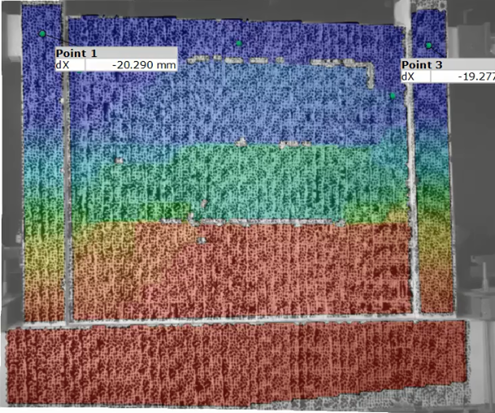
Specimen made from the reinforced-concrete frame and unreinforced masonry infill wall. The front side is painted white with randomised black dots, creating a stochastic pattern for the photogrammetrical measurements using ARAMIS. The back side of the specimen is only painted white, so the cracks can be drawn.
Here is the close-up of in-plane loading.
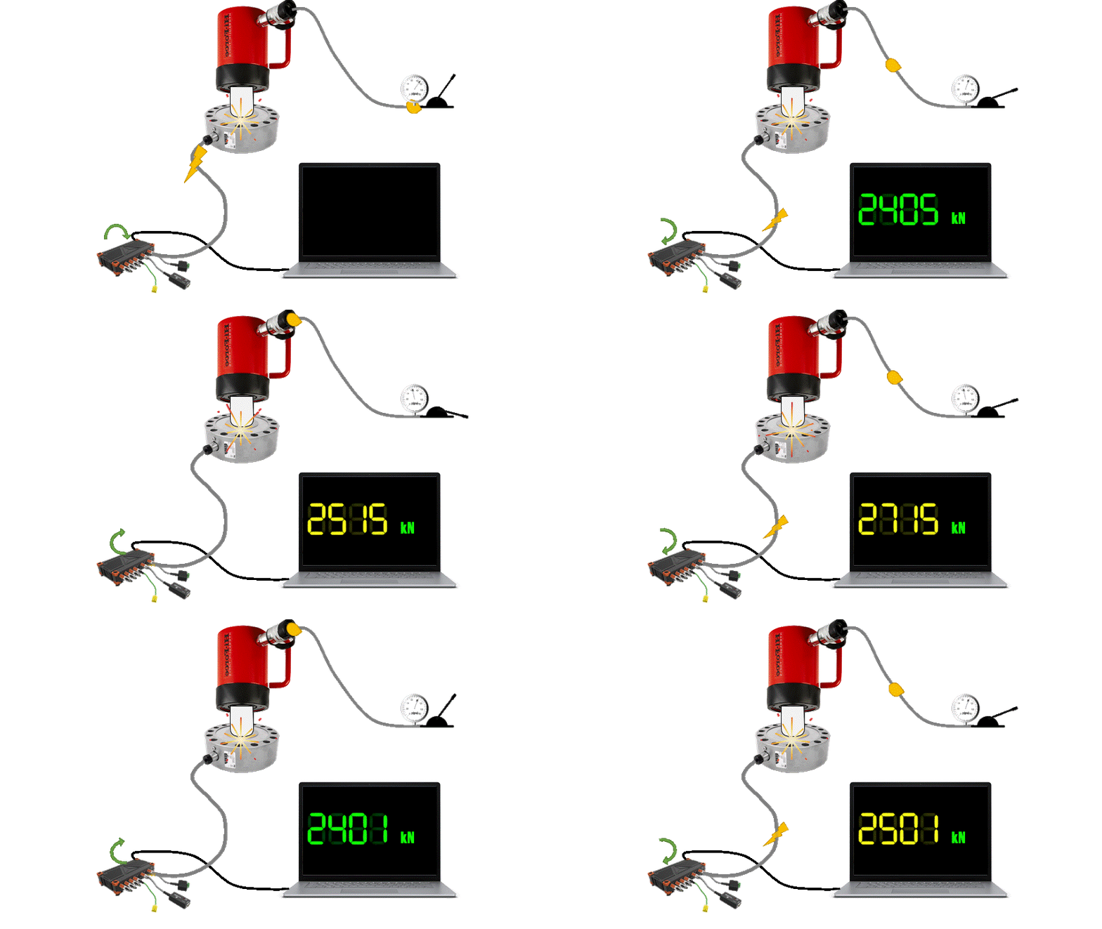
In this slide, you can see the device used to implement and measure the in-plane load. The animation below shows the process in action.
The electric hydraulic pump pumps oil into the press, which then extrudes the piston and presses the load cell. The load cell converts the change in pressure into a change in voltage, which is sent as an analog signal to the data acquisition box. The box converts the analog signal into a digital signal (ADC) and, using special software, the change in voltage is correlated with a change in force.
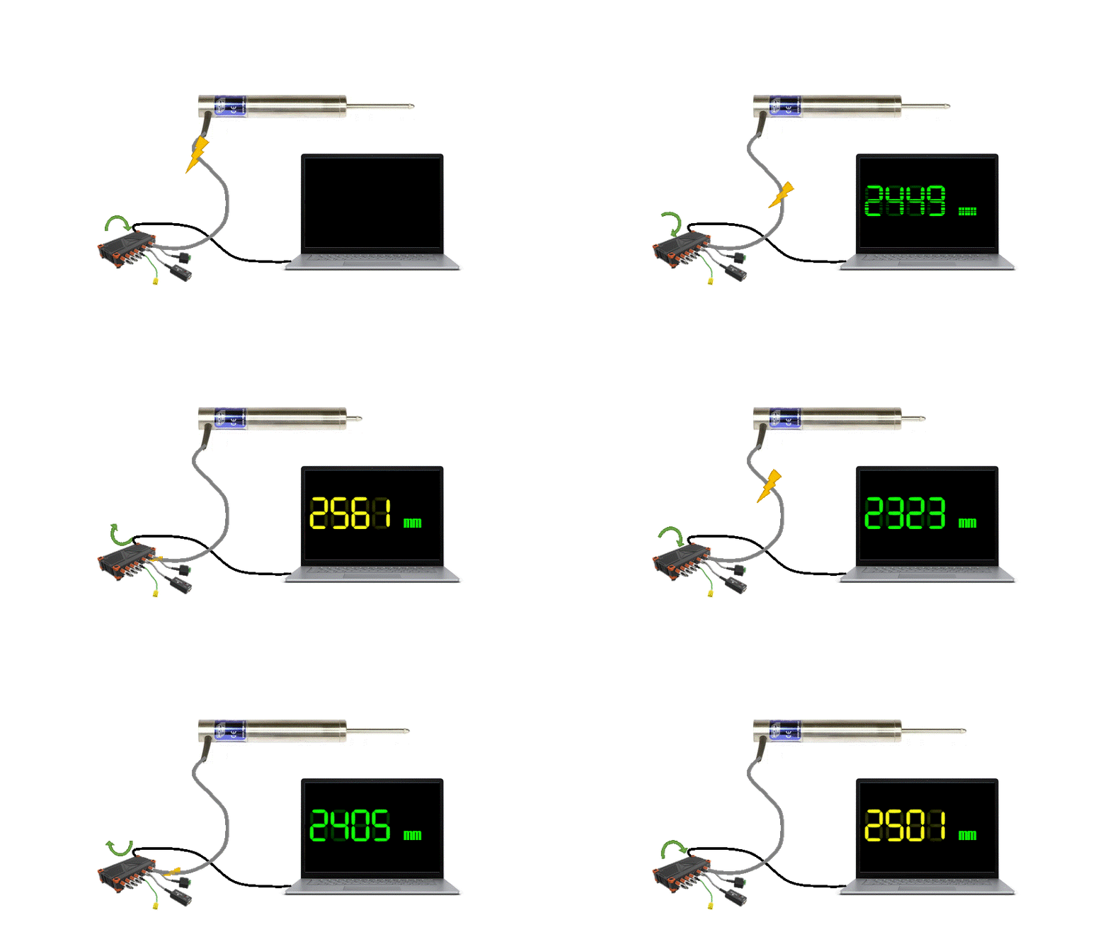
Above the press and load cell, an LVDT is placed. The working principle of an LVDT (Linear Variable Differential Transformer) is based on electromagnetic induction. It consists of a primary coil, a secondary coil, and a ferromagnetic core that moves inside the coils. When an alternating current is applied to the primary coil, an electromagnetic field is generated that induces an electrical signal in the secondary coil.
The movement of the core changes the relative position of the secondary coil with respect to the primary coil, which changes the electrical signal in the secondary coil. By measuring the change in the electrical signal in the secondary coil, the displacement of the core can be determined and, therefore, the displacement of the test specimen can be measured.
The LVDT then sends an analogue signal to the data acquisition box that converts the analogue signal to a digital one (ADC). Then the data acquisition box sends data to the PC software that correlated the voltage change with displacements. This is also presented in an animated iconography below.
The raw data collected during the experiment underwent correction to account for any rigid-body movement. This correction process is an essential step in ensuring accurate results. Once the data was filtered and corrected, load-deformation diagrams were plotted to showcase the relationships between the load and deformation. From ARAMIS and hand-drawn cracks, crack patterns in the specimen were established, allowing further analysis and interpretation of the results.
The FE model will be calibrated against the load-deformation and crack pattern data collected from the tests performed on the reinforced-concrete frame and unreinforced masonry infill wall. This will ensure that the model accurately represents the system's behaviour under various loads, and the results can be used to make predictions and validate the design. The calibration process will involve adjusting the parameters in the model until the predicted results match the experimental data. The process will help identify the most influential parameters and their effects on the system's overall behaviour. The calibrated FE model can be used for further analysis and design optimisation.
Here gravity loads are being implemented and measured in the same manner as the in-plane ones. The gravity load simulates dead and live loads from the prototype structure i.e., from floors above. In addition, it has roller support made from steel bars and plates, so the test specimen can translate in the in-plane direction.
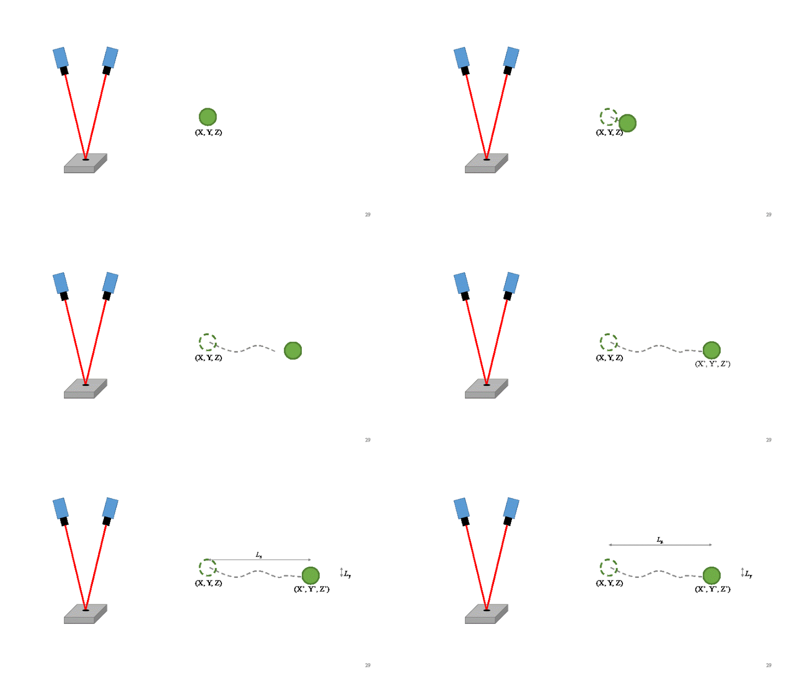
Computer for proccesing photogametrical data from ARAMIS. The working principle of ARAMIS involves capturing multiple images of a target or dotted pattern painted on the test specimen. The photos are then processed to determine the precise position of dots in each image, which allows for calculating the displacement of the test specimen.
The principle is based on the theory of stereo vision, which involves capturing images of an object from, in this case, two viewpoints (the cameras). By analysing the relative position of the target or dotted pattern in each image, the system can calculate the three-dimensional displacement of the dots and, therefore, the deformation of the test specimen. As presented in the animated picture below.
ARAMIS uses a high-speed camera to capture multiple images of the target or dotted pattern at high resolution and advanced algorithms to process the images and determine the displacement. The system provides highly accurate and precise measurements of the deformation of the test specimen without the need for any physical contact.
With the displacements, the software can recalculate them into von Mieses strain. The von Mieses strain is not considered based on its strain value since the hollow clay masonry units are orthotropic. Instead, it is used to show the crack patterns since the strain accumulates where the cracks are formed.
ARAMIS cameras are high-speed, high-resolution cameras used in digital image correlation (DIC) systems. They capture images of a test specimen during an experiment, which are then analysed to determine its deformation and displacement. ARAMIS cameras provide precise and detailed data, allowing for non-contact and full-field measurements.
The reaction frame is a crucial component in testing and helps balance the test specimen's applied loads and forces. It provides stability during the experiment and prevents unwanted movement, ensuring the results' accuracy and the setup's safety. Reaction frames are designed to withstand the expected loads and are used in various experiments involving cyclic or static loads. The reaction frame is fixed to the reaction wall and floor.
The reaction floor is an essential aspect of any testing setup involving the application of loads and forces. It serves as a stable base for the test specimen and helps to counteract unwanted movement during the experiment. The reaction floor is designed to withstand the expected loads and provide a secure foundation for the test setup. Its purpose is to ensure the accuracy of results and the overall stability of the experiment, making it a critical component in any testing scenario.
A reaction wall is a support structure used in testing to counteract the loads and forces applied to a test specimen. It provides stability and prevents the specimen from moving during the test. Reaction walls are commonly used in experiments involving cyclic or static loads, and are designed to withstand the expected loads and forces. They play a crucial role in ensuring the accuracy of the test results and the safety of the experiment.
Macro modelling of frames with masonry infill walls involves creating a model of the entire structure at a high level of abstraction, focusing on overall behaviour and load distribution. It is used to obtain a general understanding of the structure's behaviour and to provide an overview of its response to external loads. Usually, the model is composed of a frame element and a compression strut that simulates the effects of the infill wall.
Meso modelling is a step up from macro modelling and involves a more detailed representation of the structure's components, including the frames and masonry infill walls. This level of modelling is used to obtain a deeper understanding of the structure's behaviour, including the interaction between components and the distribution of forces and deformations. Usually, the infill wall is modelled as a shell or a plate element.
Micro modelling is the most detailed and precise level of modelling and involves representing the structure's components and materials at the smallest scale possible. This level of modelling is used to analyse the behaviour of individual components and materials and to predict their response to external loads. Micro-modelling is often used in combination with other levels of modelling to provide a complete understanding of a structure's behaviour.
In this virtual lab session, we will delve into the micro-modelling approach, which was utilised in scientific research to extract the highest level of detail from simulations.
In the simulation of frames with masonry infill walls, common finite element software programs include Abaqus, ANSYS, Atena, and LS-DYNA. These software programs use a finite element method to model the physical behaviour of the system, allowing for the analysis of stress, strain, and deformation. They offer a range of modelling capabilities, including material models for concrete, masonry, and reinforcement and interface gap models for modelling contacts. These programs are widely used in engineering to analyse structures and provide a robust platform for simulating frames with masonry infill walls.
Here, the Atena software from Cervenka Consulting firm was used. Atena software is a finite element analysis tool used in civil and structural engineering to model and analyse complex structures, including those with masonry infill walls. The software considers the non-linear behaviour of materials and environmental conditions to simulate the behaviour of the structure under various loads. Engineers can calculate stresses and strains on different components and evaluate the distribution of forces throughout the building to make informed design decisions and ensure the structure's safety, stability, and durability. Atena's advanced features, such as adaptive meshing and multiphysics simulation capabilities, make it a powerful tool for engineers and researchers.
Converting a physical specimen into a finite element model typically involves several steps. First, the specimen's geometry must be accurately measured and modelled in the software. If there is symmetry, one can exploit that by adding supports, as the stresses and strains are usually just mirrored images. By doing so, the calculation time is significantly saved.
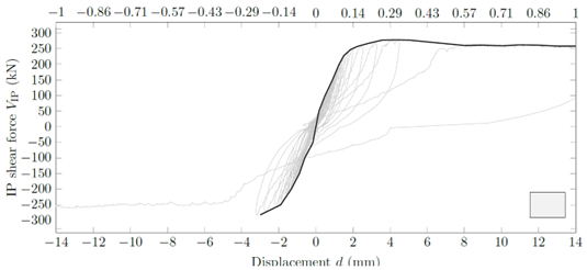
Next, the material properties of the materials used in the specimen must be determined and input into the software. This information can be obtained through testing and experiments or by using values found in the literature. In this example, we had tests of each material involved in the specimen and that of the in-plane test that you can see on this screen.
Once the geometry and material properties have been established, boundary conditions must be defined to reflect the conditions of the physical specimen. This includes constraints, such as fixed or pinned supports, and loads, such as gravity or externally applied forces.
Next, the finite element mesh must be created, dividing the specimen into smaller elements suitable for numerical analysis. The mesh must be fine enough to capture important details in the specimen, but coarser elements can also help speed up the calculation time.
Finally, the finite element analysis is performed using the software, in this case, Atena, using the defined geometry, material properties, boundary conditions, and mesh. The analysis results can then be compared to the results from physical testing to validate the model and refine the material properties as necessary.
In summary, creating a finite element model of a physical specimen requires understanding the specimen's geometry, material properties, and loading conditions, as well as a detailed mesh and proper analysis setup within the software.
In the simulation of frames with masonry infill walls, solid finite elements are commonly used to model the solid components, such as concrete, steel, and masonry units. These elements can accurately capture the mechanical behaviour of the materials under load and deformation, providing more detailed and accurate results than other elements, such as shell or beam elements. Using solid elements also enables the modelling of complex geometry, material heterogeneities, and non-linear behaviour of the materials.
These material models have properties such as strength, stiffness, and degradation, which are inputted into the finite element model. The properties can be obtained from mechanical tests on the actual building components or from numerical data from literature and/or calculations. The former provides the most accurate representation of the material behaviour, while the latter may be used when actual test data is unavailable, or the parameters are purely computational. Regardless of the method used to obtain the properties, the material models play a crucial role in accurately representing the mechanical behaviour of the building components, which is critical in accurately predicting the behaviour of the building under load. Here, most mechanical parameters were obtained by tests, while others were by calculations or recommendations from the literature.
Elastic plates were used for point force input, to account for large deformations, and to avoid singularities. These elements are modelled as elastic plates to accommodate Saint-Venant’s principle.
Solid elements are used to simulate masonry units. A CCNonlinearCementitious2 material model was used to simulate it. CCNonlinearCementitious2 is a material model used in the Atena software developed by Cervenka Consulting to simulate structures with concrete and masonry components. This model is based on non-linear behaviour of cement-based materials and provides a comprehensive representation of the mechanical response of concrete and masonry under various loading conditions. The model includes cracking, damage, and degradation of concrete and masonry, as well as their behaviour under cyclic and monotonic loading, making it helpful in simulating the behaviour of structures such as frames with masonry infill walls.
The CCNonlinearCementitious2 material model is also used to simulate concrete. The CCNonlinearCementitious2 material model from Atena software by Cervenka Consulting is a complex material model that considers the non-linear behaviour of concrete. This material model can be used to simulate concrete in a finite element analysis, and it incorporates various features such as creep, shrinkage, cracking, and reinforcement corrosion. It is designed to provide a high level of accuracy and detail when simulating concrete structures, and it can be used to model both plain and reinforced concrete. The model is based on advanced mechanical and chemical theories and considers various parameters such as temperature, humidity, and load history.
Contact elements are a crucial component in finite element simulations, especially when simulating complex systems like frames with masonry infill walls. They are used to model the interaction between two or more bodies that are in direct physical contact with each other. Contact elements are used to simulate the friction, normal, and tangential forces that occur between the solid elements. The proper use of contact elements can significantly improve the accuracy and realism of the finite element simulations for frames with masonry infill walls.
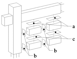
The micro model of a masonry infill wall is composed of 3D solid elements bound by 2D contact interface (gap elements). The contact elements between the concrete solid elements are perfect contacts. Perfect connections between concrete solid elements refer to an ideal scenario where the concrete elements are connected without any slip or gaps between them, resulting in a continuous structure.
The interface gap elements model the contact between the mortar and masonry by simulating the gap between them as a separate element. The gap is characterized by its geometry, friction, and other mechanical properties. The behaviour of the gap is then modelled in response to the loads and deformations of the surrounding elements, simulating the interactions between the mortar and masonry. This allows for a more accurate representation of the behaviour of the system and its response to various loads and deformations. Note that the interface model does not simulate the mortar, but rather, the masonry-mortar conjunction.
The a and c parts from the picture above represent bedjoints. The distinction is that the c bedjoints have interlocking functions implemented while the a ones do not. Mortar interlocking occurs when hollow masonry blocks are joined together using mortar (bottom photograph). The mortar fills the gaps between the blocks and creates a stronger connection between them. This results in a more shear-resistant bond and causes the masonry to break under tension instead of sliding when tested. The shear interface function, in this case, has both a hardening and softening part, while the tensile function only has a softening part. Hence, the a bedjoints are joined to concrete i.e., no interlocking. The same goes for headjoints, marked with b. The difference between the head- and bedjoints is also in their stiffnesses, as the masonry units, due to voids, have orthotropic mechanical characteristics.
Rebar was modelled as a 1D truss element with a material model that follows a bilinear law with hardening. This means that the rebar’s behaviour is modelled as having both linear and non-linear components and that its properties change as it is subjected to loads over time. The hardening aspect of the model accounts for the rebar’s increasing resistance to deformation as it is subjected to larger loads. Using this material model, the finite element model can accurately represent the behaviour of the rebar under various loading conditions and provide valuable insights into the overall behaviour of the masonry structure.
The FE mesh is a crucial aspect of the finite element model as it determines the resolution and accuracy of the calculations. The mesh represents the physical model in the virtual world, so the size and shape of the elements directly affect the simulation results. A coarser mesh with larger elements will result in faster computations but with less accuracy and detail. On the other hand, a finer mesh with smaller elements will produce more accurate results but will require more computational time. Therefore, a balance must be struck between computational efficiency and accuracy, depending on the specific requirements of the simulation. The FE mesh’s quality also affects the calculations’ stability and the ability to capture localized behaviour, such as cracking or yielding.
Here, a coarser mesh was used with cube elements on most of the solids so the calculations could run faster. Thought, for cyclic simulations, they’ve lasted up to a week.
Boundary conditions are imposed on the finite element model to represent the actual physical conditions of the modelled system. These conditions are applied to the model’s boundaries to determine how the structure should behave under specific loads or constraints. Boundary conditions include fixed supports, displacement constraints, force loads, and temperature loads. The choice of boundary conditions and their application significantly impact the simulation results’ accuracy. Therefore, choosing the proper boundary conditions is crucial to obtain accurate results.
Pinned support with all translations that simulate the foundation. A fixed support is formed by having two pinned supports on parallel edges, as it does not allow the finite element to rotate.
Gravity load and column supports. The gravity load was calculated from a prototype structure and added up to 365 kN on each column. Due to the step-wise calculation of the Newton-Rhapson method, the load was added in 5 steps. Roller support was then activated to maintain the gravity force throughout the simulation.
The in-plane force was input into the simulation software in a manner that mirrored the way it was applied during physical testing. This involved incrementally adding ±5 kN per step, and repeating the process twice to accurately represent the applied force.
During the physical experiments, a gravity load of 365 kN was applied to the columns with steel rollers. While the steel rollers allowed for translation, friction force in the opposite direction to the translation occurred due to the high normal load. The friction of the steel rollers was minor, but when combined with the gravity load, the friction force added up to approximately 10 kN for one column. This friction force was modelled in the finite element simulation as a multi-linear spring with a stiffness calculated by dividing the sum of the two friction forces (from the two columns) by the area of the beam where the spring was placed.