Assignment I:
Variable Resistance Piano
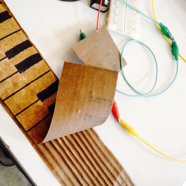
The first assignment was to build a fancy variable electronic resistor. I built a table-sized piano made of a wet cardboard. The resistance increases with the distance between the cable connection. The internal structure of the cardboard affect on the current.
The current flows through a basic 555 timer circuit - creating square wave oscillations which can be played on a speaker. By changing the distance between the connection on the cardboard you can change the resistance and the pitch of the tone.
Assignment II:
The Boiling Water Indicator
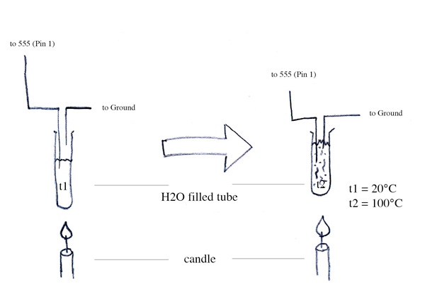
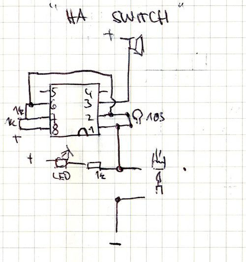
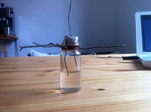
The second assignment was to build a fancy electronic switch. I built a construction of a basic 555 timer circuit (creating a square wave oscillation connected to a speaker) which power on/off is triggered by a connection of two contacts. I put the contacts into a water filled glass tube which was set over a flame. Immediately after the water is boiling the expanded water volume let current pass to the circuit.
Final Assignment:
The LED Pulse Sensor
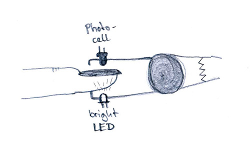
For my final assignment i developed a LED pulse metering sensor. The sensor is made out of a bright LED, a photocell, two 546B transistors, some fixed resistors, a variable resistor (potentiometer) and an array of 9 LED which flash when blood goes to your fingertip.
<videoflash type="youtube">KmyUX5ywaMg|700|450</videoflash>
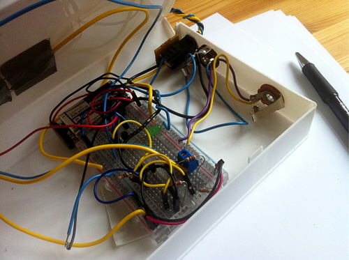
The basic principle is the translation of the human blood flow into an electronic value. The photocell changes its resistance up to the light going into it. The resistance changes if fresh blood comes through your fingertip because of the decreasing of passing light. Two 546B transistors (operation amplifiers) are comparing and switching the LED array on and off. Up to the size of the fingertip the sensitivity of the photocell (resistance) has to be set with a potentiometer. Due to some experiments and experiences i decided to use a combination of a fixed and a variable resistor (the poti). The variable resistance can be changed from 0-470 ohms which allows a fine threshold setting for the fingertip size.
The sensor clamp is put in a box to avoid daylight coming into the photocell and bringing unwanted resistance values into the circuit.
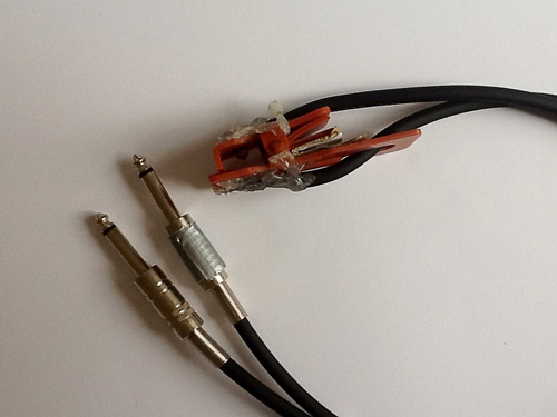
For transportation and handling the sensor clamp and box contacts were soldered on two 6.3mm audio jacks and inlets.
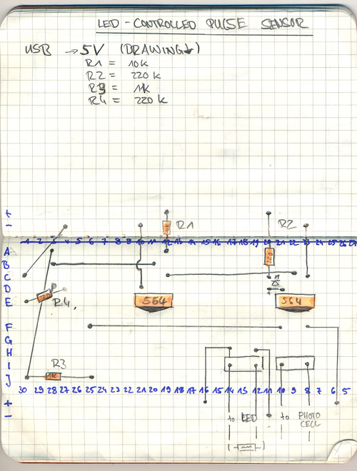
Breadboard Sketch (5V Arduino resistance values):
I also decided to connect a arduino board to read the values in a processing sketch (video below). With programs like Processing or Pd the pulse can change any value and transform it into graphic, sound etc.
<videoflash type="youtube">cCaQeeis1ug|700|450</videoflash>
Additional Work:
The 555 Squarewave Synth
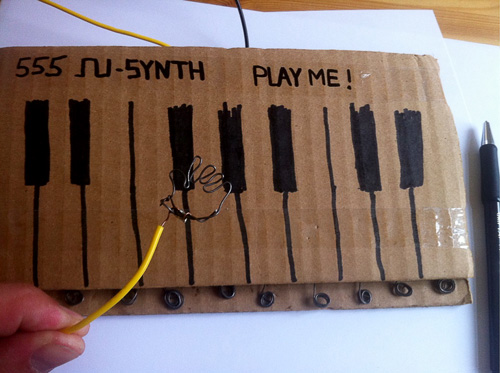
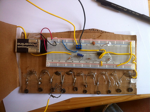
This is another version (improvement?) of my wet cardboard piano without the need of water. I put another 555 mono stable timer and put multiple fixed 1k ohms resistors between pin 7 and 6. The leads of the resistors are soldered to some copper wire which is seen under the fake piano keys. The synth can be played by connecting the copper-wire hand (pin 7) and the different leads of the keys (pin 6). Its also possible to take the hand into your hand and play the piano by touching the copper curls on the bottom. Due to the resistance of the human body the pitch of the tones is much more lower than in the first mode.
<videoflash type="youtube">7B_43t2jaZo|700|450</videoflash>
